Billy Shope;GM F body torque arm?

Shocks, Springs, Brakes, Frame, Body Work, etc

Moderator: Team

Ed-vancedEngines

Post by Ed-vancedEngines »

Image

I can see something like that working for a driver or a car with low horsepower. It is essentially in charastics like using a short, very short ladder bar and mounting the front pivot high.

I have a set of ladder bars that are using that same short link at the top but they are not that short and are very well braced. One of thse days I will see if anyone wnts to buy them.

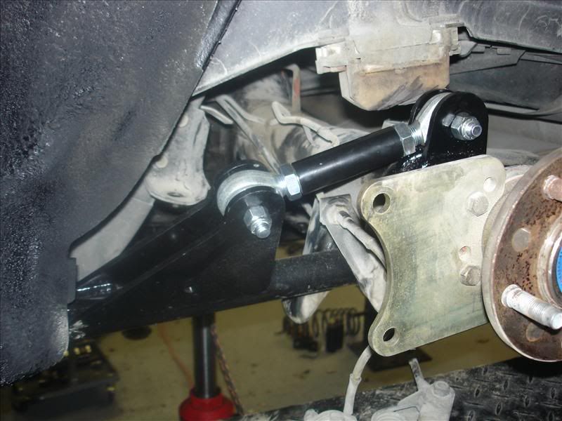
Tying the top to the bottom is nothing new at all. Problems I see with that is it ends up being a single round bar on each side to handle all the torque and suspension action. Can work with low power.

The same basic idea from a structural and suspension viewpoint was done back in 1964 by Ford Motor Company on the Comet Super Cyclones and the Ford Thunderbolts. EXCEPT Thiers was stronger. They tied the rear end housing to a single bottom bar with welded gussets and used a single front pivot on each side, but their single bar was a piece of 2 x 3 inch square tubing. That little round bar of theirs in the pic just won't do the job if you have power and traction.

No way under the sun you can make that think work with high power with tires hooking.

I don't see anything wrong with his out board shock mounting but I quetion why. If it is to be able to mount a coilover with a long travel i understand. Doesn't leave much room for tires though.

I think it would be as economical to just do a full changeover to either a 4 link or ladder bar setup for what that kit is selling for though.
System Includes:
Two lower control arms made from 1.50” diameter thick walled tubing (1/4" wall) with oversized bushings pressed into the ends, two double adjustable upper control arms made from 1.25” diameter thick walled tubing (1/4" wall), four upper control arm mounting brackets made from 1/4” thick laser cut steel, all necessary hardware, and detailed instructions.

* System requires welding of the new upper control arm mounting brackets to the axle.

* System may require minor trimming of the wheel well for clearance for the upper control arm mounting brackets.

No doubt that short high instant center will hook.

My thoughts are that the company or person that has come out with this has over engineered himself.

Ed
Last edited by Ed-vancedEngines on Sat Aug 11, 2007 11:58 am, edited 1 time in total.
Ed-vancedEngines

Post by Ed-vancedEngines »

I really don't understand why those guys over on that LS 1 Board are even trying to get rid of their torque arms.

Madman at Thunder Racecars in Louisiana is getting a 5.00 and better 1/8 mile times with his Torque Arm True 10.5 car that is owned by Paaco.

I think if they can get a Torque Arm Suspension to hook with 2,000 hp on a tire 10 1/2 inches wide. (Est) that those guys withg their puny stuff should be able to also. Not trash talking tem. Just trying to make a point.

Ed
Makina
New Member
New Member
Posts: 15
Joined: Wed Aug 01, 2007 7:20 pm
Location:

Post by Makina »

I don't understand it either <shrug>.
User avatar
BillyShope
Pro
Pro
Posts: 343
Joined: Thu Apr 14, 2005 9:15 am
Location: Orlando, FL
Contact:

Post by BillyShope »

svocapri, with a proper free body diagram, the torque to which you refer always reduces to link and tire patch forces.
http://home.earthlink.net/~whshope
1989TransAm
Guru
Guru
Posts: 15481
Joined: Thu Feb 15, 2007 8:43 pm
Location: Cypress, California

Post by 1989TransAm »

Thanks for the replies. The cars in question would be under 500 horsepower at the motor. Mostly street with the occaisional strip passes.
User avatar
BillyShope
Pro
Pro
Posts: 343
Joined: Thu Apr 14, 2005 9:15 am
Location: Orlando, FL
Contact:

Post by BillyShope »

Ed-vancedEngines wrote:I really don't understand why those guys over on that LS 1 Board are even trying to get rid of their torque arms.
Ed
Yeah, there's certainly nothing basically wrong with the torque arm. And, as you pointed out, it works!

Right next to the KISS sign on the shop wall should be: IF IT AIN'T BROKE, DON'T FIX IT.
http://home.earthlink.net/~whshope
Makina
New Member
New Member
Posts: 15
Joined: Wed Aug 01, 2007 7:20 pm
Location:

Post by Makina »

Well, I'm finally getting a chance to do my own stuff again. Been doing side jobs to pay for parts.

Designed some new mounts for the "torque arm". Did a finite element stress analysis on the links. They're going to be made of 1/4" thick mild steel.

3000lb load at the bottom hole.
Image

3000lb load at the top hole.
Image

Factor of safety of 1.28, not much room to grow but with two of them they should handle just about anything I throw at them.

Mocked it up with the Spohn hiem joint to see if the holes were spaced properly between the bottom mount and the rod end mount. Printed at a 1:1 ratio, so it's the actual size.
Image

Gotta shift the holes up another 1/2" or so to make sure it clears.

Already got the plate waiting, going to have it waterjet cut once I finalize the design.
Image

Redesigned the link to clear the mount and the rod end

Image

but ran into a problem

Image

Image

Looks like it's not going to clear the driveshaft with a bolt in there.

I designed this new crossmember awhile back.

Image

It's a preliminary design, and I already see some stuff I need to change, the perforated links being one of them....

Going to tie the crossmember ends onto the subframe connectors, weld on the pads to the crossmember and bolt them to existing mounting points in the chassis for additional support.

As with anything else it's gonna take time and $$$ to do it. One of which I'm out this month, and with school starting (masters degree) I'll probably be limited on the other. Going to be hard mocking it up, making sure it's right and finding (the hard part) a competant shop to bend up the tubing as I need it. I can cut down the spacing between the links so that I can clear the driveshaft with no problems and get the adjustability I need. But at this point I'm not too sure what I need, and probably won't until I start taking some measurements of angles etc.

With this small hiccup I'm just going to use the link that came with the setup and weld on (shock mount, swaybar mounts, lower control arm relocation brackets etc) the rest of the parts and see what she does at the track and take it from there.

I'm jones'n to get back out there.

I sill plan on doing the kinematic animation but not there yet.
Ed-vancedEngines

Post by Ed-vancedEngines »

Man' I am impressed. I wish I could do this. You should have a bright future ahead of you. Is there any reason you can't move the forward attaching point to the left by a littlle and capturing a nut in each hole maybe use a double bracket on the right to capture a nut inside

You probably wouldn't need to move the front attachmnet point to the left but maybe 3/4 of any inch. I am not sure if I am explaining myself. Picture in the front you have three cut verticle plates with the holes in them. BUT. On the right side the two plates could have hex holes cut in them the same size as a small diameter nutThe nut will not extend beyond the outside of the far right plate. The next plate to the left will also capture the nut but the nut head will not extend any further to the left than that plate. Nuts are ground for a weld and welded into each plate. Run a tap into the nuts after welding. the second plate will be the surface the front bount bushing will be against like the left plate.

The outer side of crossmember can have a flat mounting plate with several bolt holes placed vertical for up and down adjusting if wanted. that would correspond with a mounting plate welded to the subframe connector and short in heigth with a small triangulated gusset back to the subframe connector from the bottom of the subframe mounted crossmember mounting plate.

I do not like your front mounting verticle palte with the cross member going through it. If you are planning on welding that you will lose any forward and reverse movement which is neeeded in a Torque Arm. I would like it if you came off the cross member with a short double shear tab that you can then attach your front mount verticle water jet ccut plates to. That will allow up and down adjustability of the Torque Arm but wil laso allow the front and rear movemnet it needs for suspension travel without binding.

You can also use a bushing in that heim joint and put smaller holes in your plates to give more room for more holes with a greater range of adjustment. To give you an idea, we began years ago with 3/4 bolt holes and 3/4 heims. Then we went to 5/8 sizes and now all the top professional stuff is using only 1/2 bolts and holes for 4 links. So bushing that joint down should be ok and allow more holes with wider range of adjustability.

Once agin. I am blown away at your skills and abilities. I am in envy.

Ed
1989TransAm
Guru
Guru
Posts: 15481
Joined: Thu Feb 15, 2007 8:43 pm
Location: Cypress, California

Post by 1989TransAm »

Here is a link to a video of Ed Wrights Firebird with the set up installed. This car ran a 9.95 in the quarter mile. The setup is what I linked in my previous post.

http://www.fastchip.com/Ed-995.wmv
Ed-vancedEngines

Post by Ed-vancedEngines »

As far as i know this is the World's Quickest Torque Arm Car. Doing it with a True 10.5 tire.

Torque Arms can be made to work very well.

Built by Madman Brian Jeffers of Thunder Racing in Louisiana.

Image

Image

Image
1989TransAm
Guru
Guru
Posts: 15481
Joined: Thu Feb 15, 2007 8:43 pm
Location: Cypress, California

Post by 1989TransAm »

Most impressive. Thanks for the post Ed. :)
Makina
New Member
New Member
Posts: 15
Joined: Wed Aug 01, 2007 7:20 pm
Location:

Post by Makina »

Thanks Ed, I'm flattered by your response. I do this kinda stuff on a daily basis at work depending on what needs to get done. I'm fortunate to have the ability and apply it to what I love.

This is more along the lines of what I was thinking. Keep in mind this is just a concept and not a final design. The tabs, links, crossmember can , and probably will, change.

Image

I can reduce the spacing between the links to clear some more room between the driveshaft.

Billy

I've got through your website, lots of great info and lots of calculators. On the chassis dyno, how exactly do you set it up? Do you have any pictures?

I found a local shop that has scales, hell they might even have the capability to set it up.

My wife bought the front suspension for my birthday :shock: . Definitely wasn't expecting that. Now I'll have adjustable coilovers up front so I can adjust weight distribution. I am now in a position to start adjusting this kind of stuff.

I also bought a plumb bob yesterday, some levels etc to start measuring stuff. Hopefully today I'll have all the rear suspension components that need to be welded up done. I want to start making the car tracks true on the first pass but not sure what to use as a reference.
User avatar
BillyShope
Pro
Pro
Posts: 343
Joined: Thu Apr 14, 2005 9:15 am
Location: Orlando, FL
Contact:

Post by BillyShope »

With regard to the traction dyno, I didn't think a picture was necessary. It's just a horizontal, centrally located chain out the rear. Usually, it would be a matter of lifting the trunk lid, making an access hole, and then "Y"ing out to pick up the roll cage.

If you have any questions, call or PM me.
http://home.earthlink.net/~whshope
Ed-vancedEngines

Post by Ed-vancedEngines »

Ok Guys,
Here is a sample of what I am talking about when I talk about not understanding why so many with Torque Arms are trying to get away from them.

This is the same car as in the earlier pics I posted but some real results a couple of weeks back, that can be verified.

Torque Arm Suspensions cn be made to work very well.

Ed

Number 1 qualifier at ORSCA Huntsville
General Discussion and B.S.
Post a reply 11 posts • Page 1 of 1
Reply with quoteReport this post Number 1 qualifier at ORSCA Huntsville
by madman on Mon Sep 24, 2007 2:36 pm

Finally had some success with our EZ Street Firebird. Went to Hattiesburg last 2 weeks ago to test some suspension changes. We ran a string of 5.0s 1/8 miles and ended up winning the stock suspension class. This past weekend we went to our ORSCA race in Huntsville and off the trailer ran a 5.10. First rd of qualifying she runs a 5.06. Second round we go a 5.03. final round we turned her up and she runs a 1.26 60ft and a 4.94 @ 152.70 for the number 1 spot. Sunday we made it to the semis and looks like we broke a valve spring on the pass and our driver shut it down as soon as it nosed over.

Its nice to finally be able to read the track and put a tuneup in her and she responds. Its time to turn the blower up and put some timing in her now!!!
http://www.thunderracing.com 877-516-7223

http://www.strikenote.com


We gonna have to get beer for the morning!!!
madman
Sponsors

Posts: 113
Joined: Mon Jun 18, 2007 6:17 am
Location: baton rouge
Private messageWebsite Top
--------------------------------------------------------------------------------
Reply with quoteReport this post Re: Number 1 qualifier at ORSCA Huntsville
by Jay Leto on Mon Sep 24, 2007 2:45 pm

Congrats. I was following is round by round on the internet.

Now we just need to get mine sorted out. Orlando is creeping up on us...


Jay
'94 Mustang BBC, turbo on alcohol. Stock suspension.


Jay Leto

Posts: 76
Joined: Sun Jun 17, 2007 8:41 am
Location: Gonzales, La
Private messageWebsite Top
car_fixer
Member
Member
Posts: 74
Joined: Wed Nov 07, 2007 11:22 pm
Location: ga

Post by car_fixer »

this is a very interesting thread, i like real time experiments, so check this out
Image


this car has a stock length torque arm, 56.5 inches if i recall correctly, its mounted to a cross member, not the trans. being that the center of lift here is the front attachment point, moving that back would reduce the amont of leverage it has on the car, thus not lifting the front as much, correct?
i realize that these cars are imperfect in design (not really ment for much over the factory hp) and the lower control arm in the rear is too low, but i cant fix that without major reconstruction, and if i wanted to do that, i shure as hell would put a 4 link in. oh and by the way the front extension is limited to 2.25 inches, struts are full stiff, and yes if you watch slow mo you can see the sparks under the car, mainly from the v band clamps on the exh. bearely dimpled the headers, i ran a 5.78 1/8th after that, ran out of fuel pump though so it only ran 9.41 1/4
Post Reply