The BMW M20 engine

General engine tech -- Drag Racing to Circle Track

Moderator: Team

Post Reply
Hairyscreech
Member
Member
Posts: 91
Joined: Sat May 05, 2012 3:50 pm
Location:

The BMW M20 engine

Post by Hairyscreech »

(Please try and ignore the red paint in some of the photos the head has been used as a painting stand for some formula Renault parts) :)

Good evening guys, (Well it is here on this side of the pond), I'm a motorsport engineering student from the uk and also do some of my own stuff on the side when time allows.
I have been lurking on and reading these boards for a while and have been meaning to bring a project thread over to here for some opinions and suggestions.

Over here in the uk there is quite a following for the 80's bmws, long story short via an e30 forum me and a couple of others have been dissecting and attempting to improve the M20 small six engine.

An awful lot has been done and looked at over the last couple of years so i will try and keep the information brief and give a link to the original thread for those that want to take a more detailed look.
Most of the background info needed can be found here : http://www.e30zone.net/e30zonewiki/index.php/M20
Or directly about the 2.8l stroker here : http://www.e30zone.net/e30zonewiki/inde ... ding_a_2.8
The original thread is here : (needs registering to see unfortunately) http://www.e30zone.net/modules.php?name ... sc&start=0
Hairyscreech
Member
Member
Posts: 91
Joined: Sat May 05, 2012 3:50 pm
Location:

Re: The BMW M20 engine

Post by Hairyscreech »

Sorry, seems this is a long post and the forum wont allow me to post it as one post.
Fatal error: Allowed memory size of 8388608 bytes exhausted (tried to allocate 1245184 bytes) in /home/speetalk/public_html/forum/includes/utf/data/utf_nfkc_qc.php on line 2

Any ideas?
Split it into a few posts?
User avatar
Stef
Expert
Expert
Posts: 661
Joined: Fri Oct 06, 2006 5:45 pm
Location: UK

Re: The BMW M20 engine

Post by Stef »

Write your post in notepad first then cut and past into 2 or 3 posts. You can post quite quickly then to keep them altogether if that's what you want.
TTV Racing - Race flywheels, clutches, drive shafts and valve guides - over 5000 applications & custom one off's or production runs - made in England.
Suppliers to GT3, LeMans, WRC, Global X-Cross, WTCC, BTCC, F3 and more!
Visit our Instagram Page!
Hairyscreech
Member
Member
Posts: 91
Joined: Sat May 05, 2012 3:50 pm
Location:

Re: The BMW M20 engine

Post by Hairyscreech »

Currently trying that, but only getting the message above?
Is there a limit for newly registered users that i haven't spotted?

Found the problem, seems a pound sign will break a post, as soon as i removed it it worked fine. :)
Last edited by Hairyscreech on Mon May 14, 2012 5:55 pm, edited 1 time in total.
Hairyscreech
Member
Member
Posts: 91
Joined: Sat May 05, 2012 3:50 pm
Location:

Re: The BMW M20 engine

Post by Hairyscreech »

Personally i have mostly been looking at the 2.8l stroked version of the m20, however there is a lot of info in the thread that is still relevant to all the other displacements.
Nearly every area of this engine is being looked at with the aim to find a few tricks and simple modifications that can bring this engine up to spec without spending a fortune on parts, custom parts would be the nice easy way out for a lot of things but the idea is more to do what we can with what we have.
(and anyway the simple answer would be to spend $5k and fit an M3 engine).

The specs of the engine in question:
84mm bore
84mm stroke (originally 75mm on the 2.5l)
Aiming for ~11:1 CR
Hp target is at least 250hp@6500 with the best torque curve possible,

One of the big issues is the rod/storke ratio, a quick and simple way of building the 2.8 is to use the 130mm connecting rods and have the block decked by 0.5mm, This leaves a r/s ratio of 1.54:1
If i stick with the stock 135mm rod then i am looking at 1.607:1 which is a bit nicer.
Trouble being this either requires custom pistons (out due to the cost over here) or a modified stock piston, a few ways have been looked at and discussed as how to go about this and its certainly a viable option.


Currently i am looking at using the whole M52B28 reciprocating assembly with the piston and possible the chamber modified to suit each other.

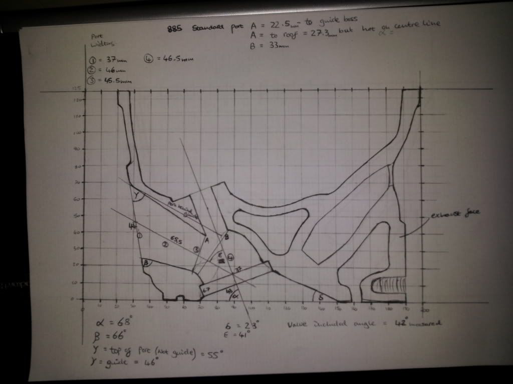
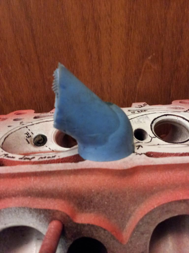
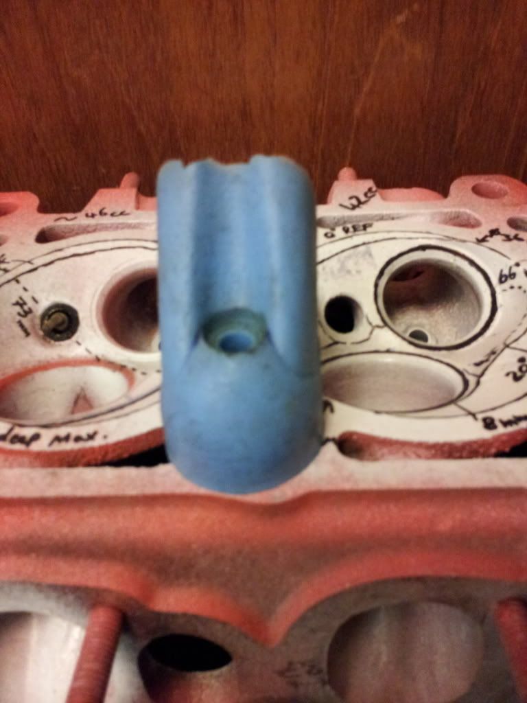
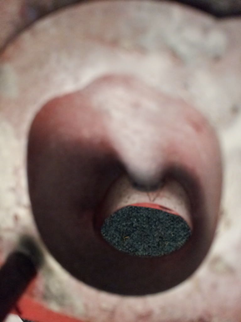
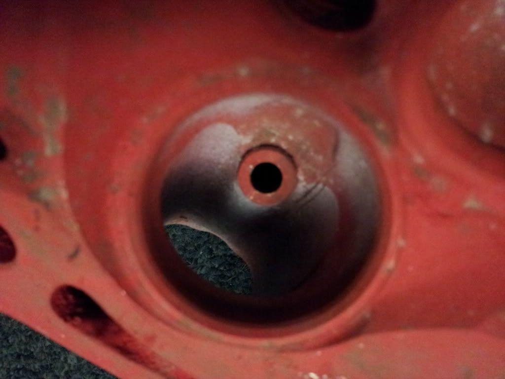
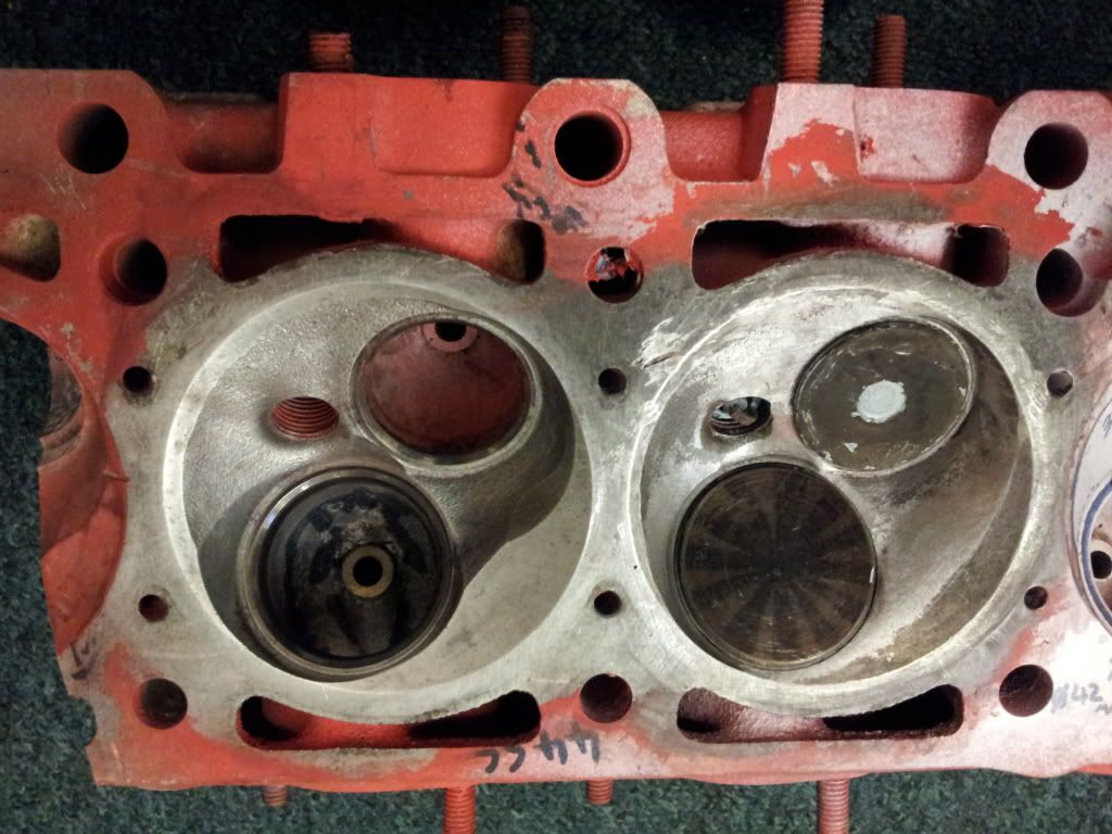
The details of the head and piston are as follows:

Image

Image

Image

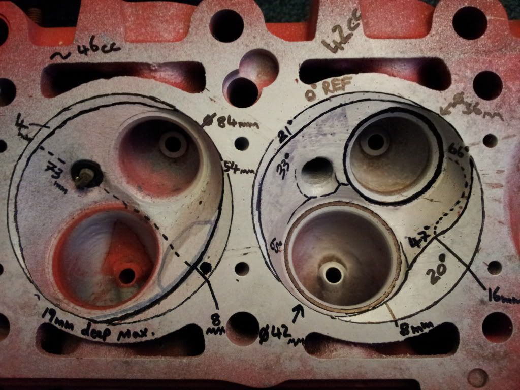
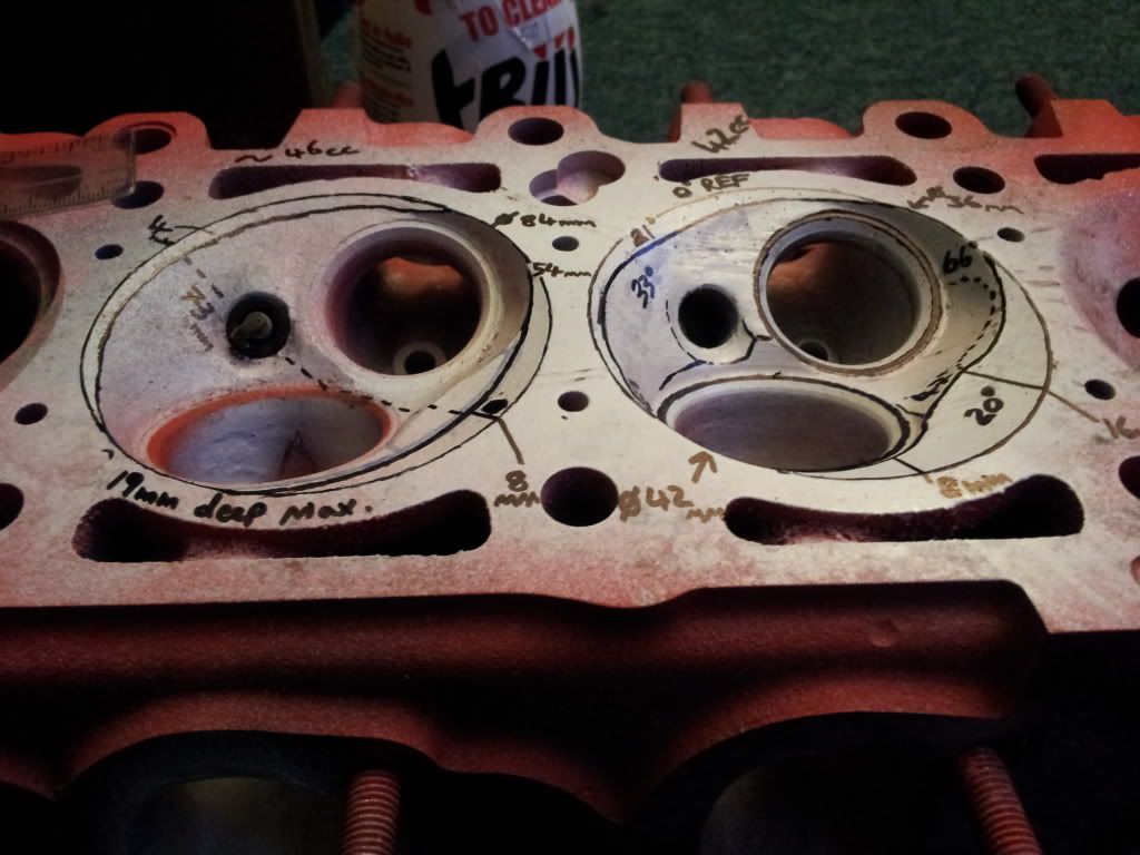
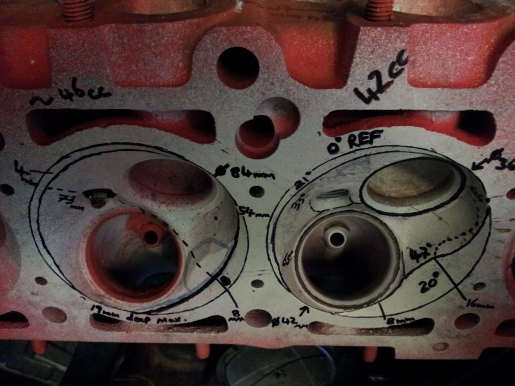
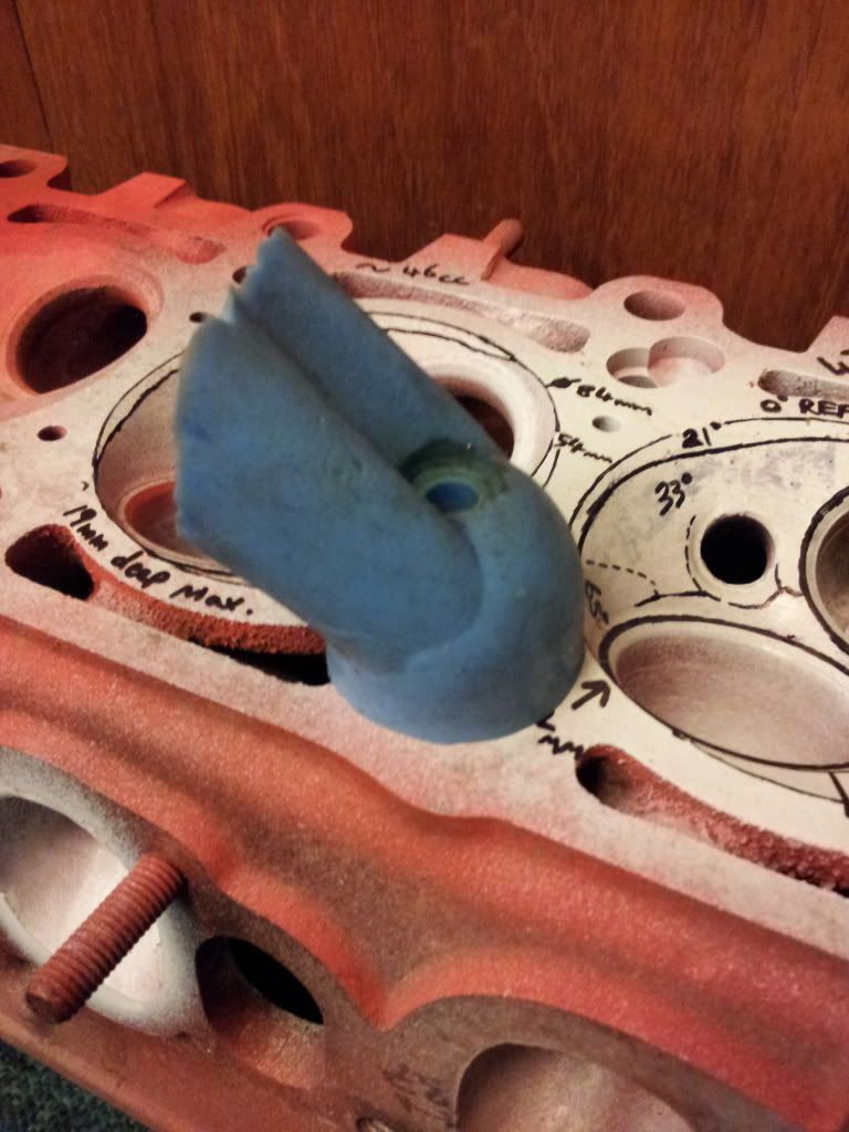
The photos above show the standard chamber on the right with the contours highlighted in black and most of the dimensions written on. The left is a proposed chamber modification which i will come back to.

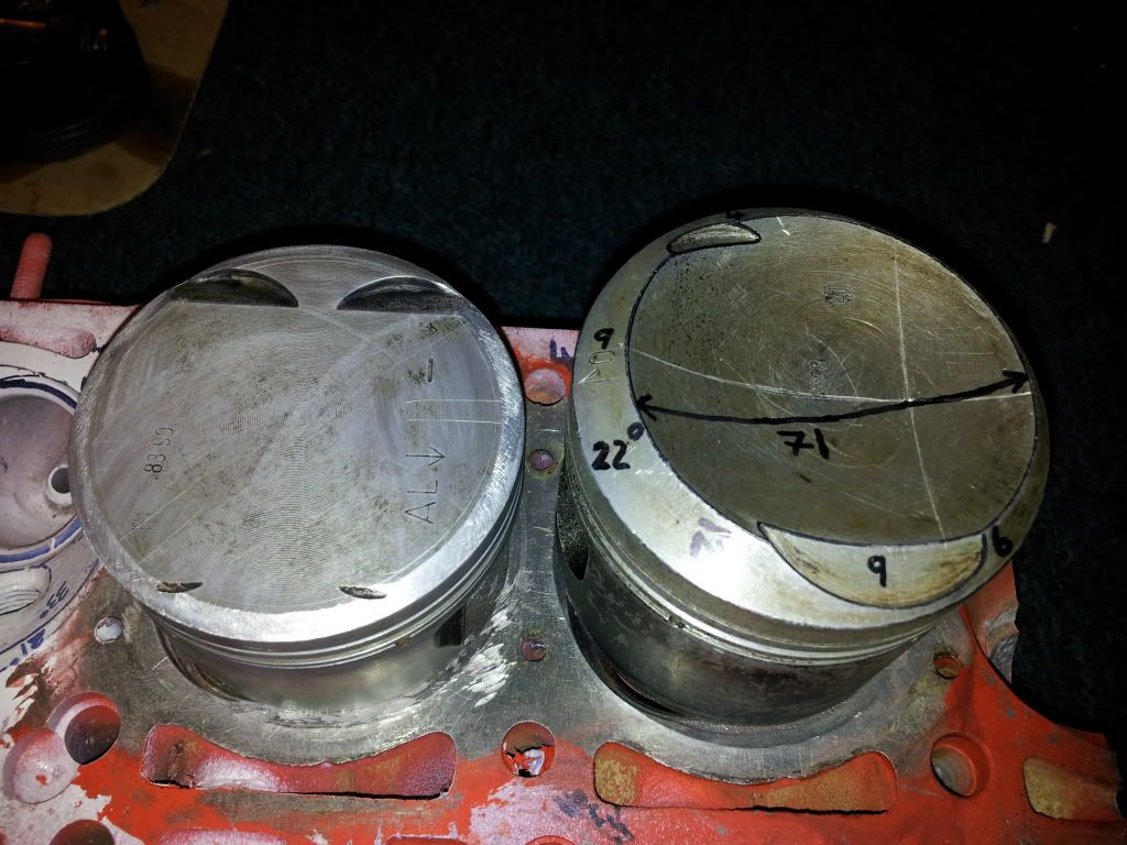
The standard M20B25 (B25 is the displacement code) Piston is a funny one and has a raised squish band with a bowl.
Image
Image
Image
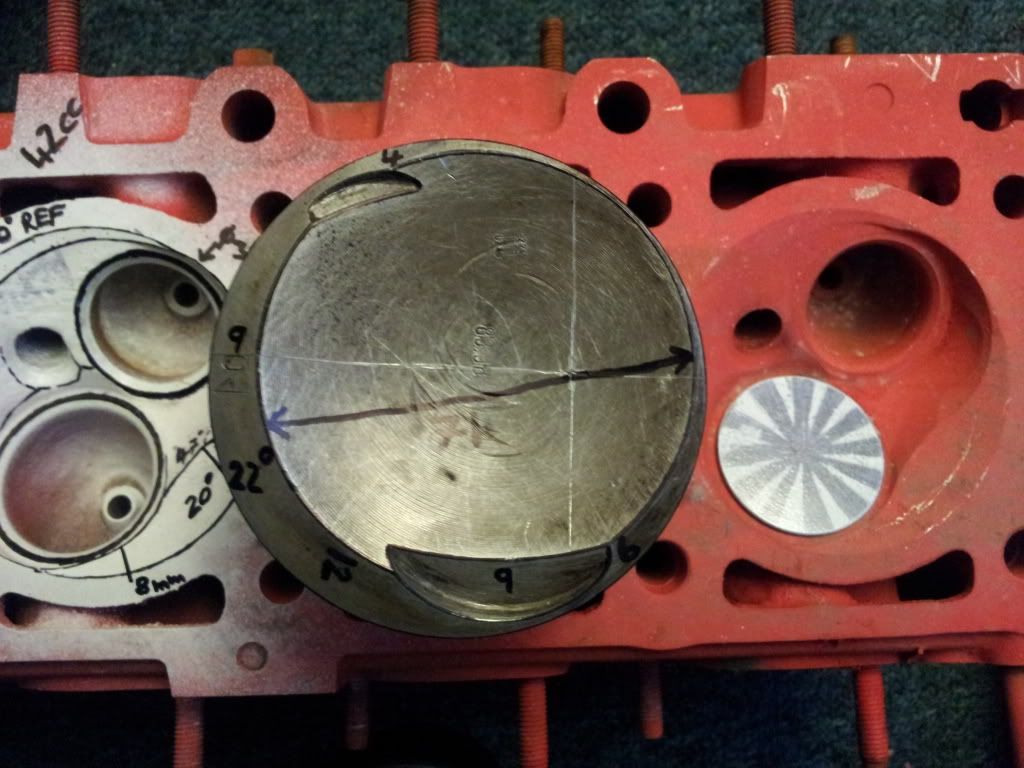
Sticking with this shape would be great but impractical without removing 4.5mm from the top of that piston of going custom.
They are also heavy old slugs and no where near any of the modern designs.
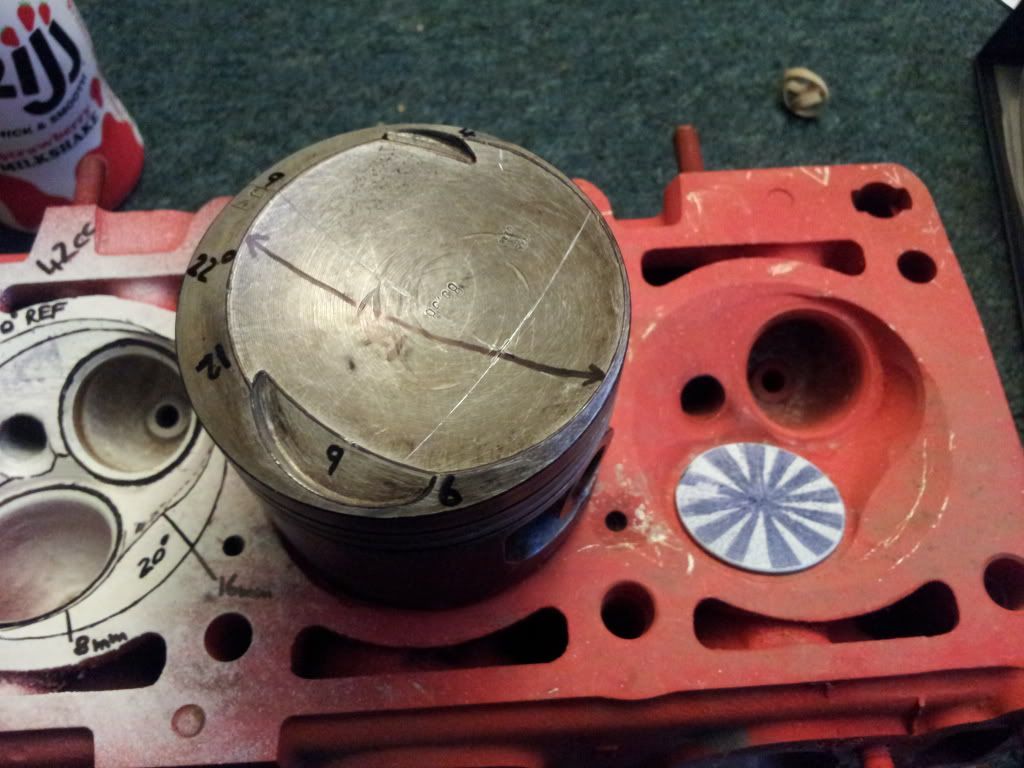
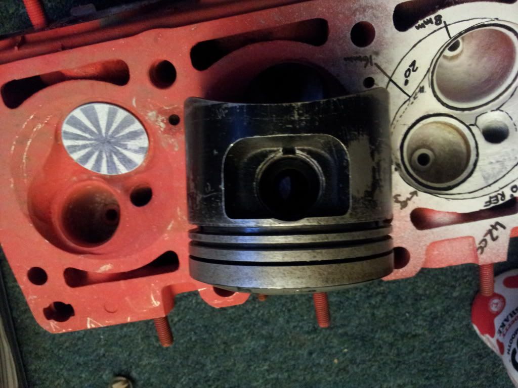
Which is where the M52B28 piston is great for a stock item.

Image
Image
Image
Image
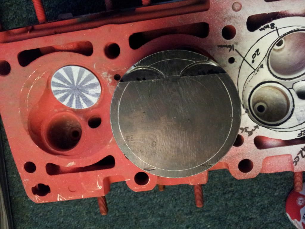
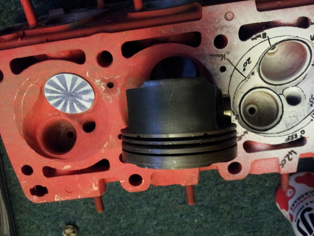
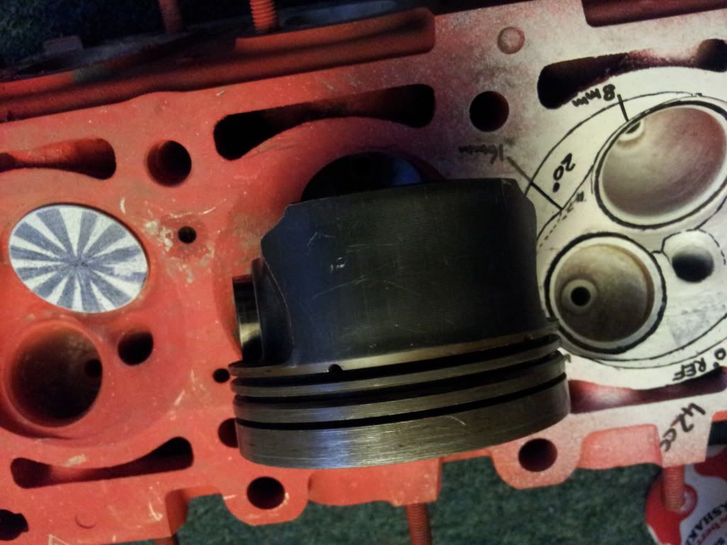
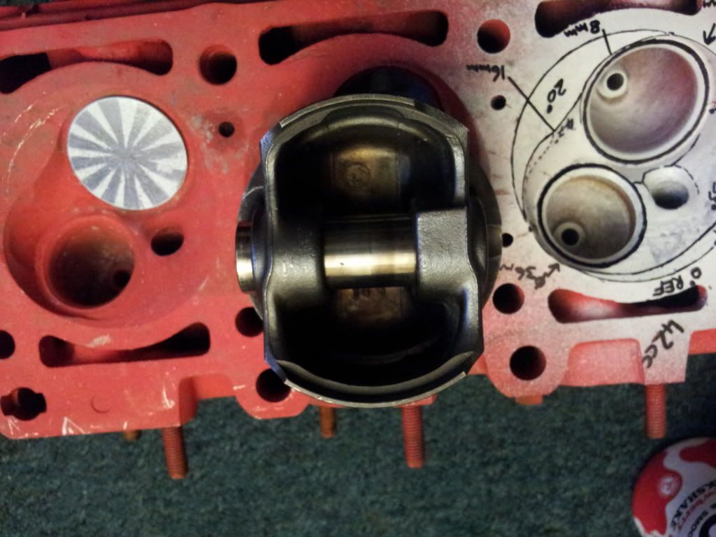
For a standard piston this one is pretty good, slightly asymmetric skirts, anti friction coating, light slipper design and 2mm offset pin and nice tight ring pack.

The current proposal is to use this piston with the edge marked by the circle scribed on the top cut down at around 21* to provide a 5.5mm squish band. (valve cut outs have been successfully cut into these for the 2V M20 in this thread : http://www.e30tech.com/forum/showthread ... 38&page=17 )

This will however mean the piston doesn't quite match the head, something i am not keen on.

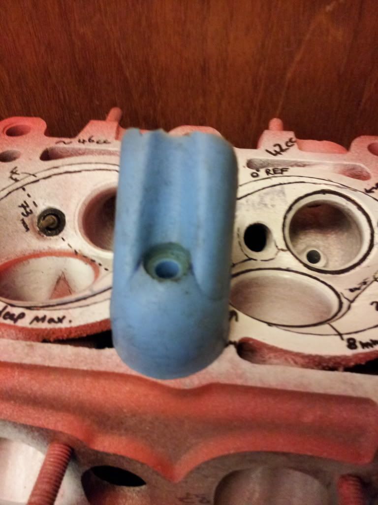
The Idea for the head is to machine the extra part of the quench pad out of the chamber as seen on the left hand chamber in the pictures above.
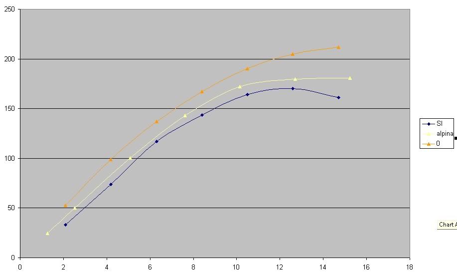
This would result in a 11.5:1 CR and is similar to a modification done by Alpina in the 1980s however they produced a full hemi with no squish and used the standard Piston crown profile :(

On the left hand chamber above there is a line marked around the squish pad showing the furthest distance from the plug.
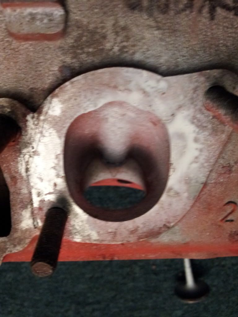
On the stock chamber the longest flame path is 54mm directly over the exhaust valve.

It would be good to hear what the collected knowledge on here thinks of altering this chamber in this manner.
Hairyscreech
Member
Member
Posts: 91
Joined: Sat May 05, 2012 3:50 pm
Location:

Re: The BMW M20 engine

Post by Hairyscreech »

The other major issue with the engine is the port flow.

I have access to a superflow 6000 and have been messing about which has taught me a lot and some modest gains have been made without huge increases in port area.

Image
This shows the flow of the standard intake port in blue, the alpina head (not measured by me) and the theoretical peak from the superflow manual in orange.
units are CFM and mm valve lift.

Multi angle seats have also been tested using plastic inserts, however the tests were done on a different M20B25 885 casting so can only be taken as the trend (as flow numbers seem lower than the first head discussed in the e30zone link)
Image

I spent a couple of hours fully measuring the ports the other day.
Image

and have taken a molding.
Image
Image
Image
Image

Pictures of a Stock port
Image
Image
Image

There are a few areas that are of obvious concern, the port seems to pinch down significantly before the guide and is poorly matched in places.
Would be interesting to see what the more experienced head builders on here make of these.

There are a lot more other photos and info in the e30zone thread and in my photobucket account, any questions and i am happy to answer them.
raceman14
Expert
Expert
Posts: 665
Joined: Mon Jul 09, 2007 11:41 am
Location: GA
Contact:

Re: The BMW M20 engine

Post by raceman14 »

Not sure if it the same heads I worked on but I used to do a pile of them for a BMW guy here in GA. I think they were 2.3 / 2.5 / 2.8 stroker engines. Some were 4 cyls and some were 6 cyls.

I lost a lot of that data on a CPU crash about 10 years ago but I recall over 200cfms using chevy valves. Not sure about the mm $hit but I think I put a 2" valve in the intake. I got decent flow up to .500" and with subsequent heads, I played with the valve job and the porting and I think we eventually wound up with 230ish on the intake. Pretty steep port, I moved the roof up and flushed the intake guides to the roof of the chamber with a little curved tail to promote swirl. I know the heads started making more HP as we went along and eventually I dropped the program cause the dude was a pain in the A$$ and started demanding work with unreasonable time demands. Like wanting stuff back in a week...or less.

I saw some of his heads at another engine builders shop and they were tickled pink to get 190cfm's.

I guess you have to have had ports flow 400-500cfm's to understand that the small stuff will pick up flow if you move the right material.
More is always better!!! Most of the time.
Norrback
Pro
Pro
Posts: 359
Joined: Wed Nov 07, 2007 2:20 pm
Location: Jeppo in Finland

Re: The BMW M20 engine

Post by Norrback »

These are common heads here in Finland and in Sweden, I have made many of them. I'll check if I have som numbers on my Flowbench computer. The SSR is to sharp/short flow separates. Gets better with a epoxy fill on the floor. The port is also normally too large.

/Andre'
doing well
User avatar
SWR
Guru
Guru
Posts: 2791
Joined: Sun Jan 29, 2006 5:39 pm
Location: Norway
Contact:

Re: The BMW M20 engine

Post by SWR »

Hairyscreech wrote:Currently trying that, but only getting the message above?
Is there a limit for newly registered users that i haven't spotted?

Found the problem, seems a pound sign will break a post, as soon as i removed it it worked fine. :)
That was an error in the board software. All is fixed now, so feel free to use any sign you want. :)
-Bjørn

"Impossible? Nah...just needs more development time"
digger
Guru
Guru
Posts: 2722
Joined: Sun Jan 27, 2008 6:39 am
Location:

Re: The BMW M20 engine

Post by digger »

Norrback wrote:These are common heads here in Finland and in Sweden, I have made many of them. I'll check if I have som numbers on my Flowbench computer. The SSR is to sharp/short flow separates. Gets better with a epoxy fill on the floor. The port is also normally too large.

/Andre'

Hence why there are other casting variants e.g. 731 that may be better suited with their smaller volume (CSA) higher SS apex but need bigger valves etc and usually more effort to get the the "all import" numbers up :wink: .

The OP casting (885) on the right and 731 on the Left with intake ports facing each other to compare. The silicone casting on the 731 port and chamber didnt turn out as crsip because i didnt clean it adequetly but it is ok for comparison

Image
raceman14
Expert
Expert
Posts: 665
Joined: Mon Jul 09, 2007 11:41 am
Location: GA
Contact:

Re: The BMW M20 engine

Post by raceman14 »

Everybody attacks a problem in a different way for a different reason. I raised the roof in the heads I worked on and found big gains. I guess epoxy on the floor is addressing some of the problems but it adds volume.

With what you have found how many cfm did you gain from floor epoxy.

A person should then prolly epoxy the floor some and then raise the roof and results should be very good. I was not charging enough on these heads to merit a lot of work. I was getting about $500 for the VJ, and some bowl work. I did the port stuff on my own just to learn what it wanted. After about 20 heads and a demanding & cheap vendor, I kicked the project to the curb. His resultant head work was marginal at best and got some pretty bad posts in Beemer forums and the business took a quick down turn.

The engine had some potential to make some decent power but for killer power I think intakes and port angles need some changes. I had good results with 50* seats when I raised the roof so straightening the port helped.

One thing most folks don't really understand is FI engine like different things in the ports than Carb stuff. It has a lot to do with the state the fuel is presented to the port, I believe carbed fuel is better emulsified with it's air mixture than High pressure raw fuel squirted into the intake and even the head in some cases.

I have always said LS carbed engines make 10-20% more power that their FI counterparts for that reason.

I would love to start a thread on that and I think I will....
More is always better!!! Most of the time.
Hairyscreech
Member
Member
Posts: 91
Joined: Sat May 05, 2012 3:50 pm
Location:

Re: The BMW M20 engine

Post by Hairyscreech »

Raceman - im sure over 200cfm should be possible with the valves enlarged and some clever port work.
good point about the mm, forgetting a lot of this forum will be working in ", i will convert as much over as i can in a sec.
I'm not sure a 2" valve would fit unless it was cut down, that would be jumping from a 42mm (1.65") to a 50mm (2") i think the largest that would fit would be a 46mm (1.82").

Re your second post - i have found a simple valve job and some bowl work helps a lot, there's a lot of bad casting mismatch in the bowl area that can be cleaned up easily and changes things quite a bit.

Andre - would be good to see how far others have got, the short side does seem far to sharp and i am going to start playing with some filling soon.

Digger - i am trying to avoid using a 731 casting at this time, the most common engine to build the 2.8l out of is the b25, which uses the 885 head, being able to work with the head already on the engine will save having to go hunting for another head. That along with the fact some regs here require the head to be the casting fitted to the engine in production makes things a bit tricky.
The other issue is that a lot of work would be needed on the 731 head to get the same chamber shape as the 885 along with needing larger valve seats and more port work, the inlet manifold will then be a mismatch to the head.
The 731 may be able to pick up more flow and better velocity but for the sake of building road/track day engines it doesn't quite seem to be worth the effort.
Hairyscreech
Member
Member
Posts: 91
Joined: Sat May 05, 2012 3:50 pm
Location:

Re: The BMW M20 engine

Post by Hairyscreech »

New question on chamber shape.

One of the things i want to do is use the 135mm (5.315") rods and pistons from the m52b28 that donates the crank shaft, using these will give me longer rods that are over 100g lighter and pistons with a much more modern design and much reduced weight.
The trouble will be to do this with the 885 head will require changes to the piston crown and the chamber in order to get a good chamber/piston match.

I have run one up just as a test piece to make my intentions clearer.

The stock chamber is on the left here it uses a shaped angled squish band, which matches up with the offset bowled piston top.
Image
Image

the other piston and chamber are the beginnings of the intended tweeks,
The plan is to run a band 4.5mm (0.1772") around the outside of the piston at 21 degrees to match the squish band of the head the valve pockets will be welded and 2v pockets cut. In order to clear the head the piston will need ~2mm skimmed from the top and this would be a way of doing it without effecting crown thickness.
The head has then been bowled out to a compact hemisphere 18mm (0.708") deep at its deepest point. To do this the changes/contours in the casting have been blended completely and the squish band on the far side of the plug has been cut back to the longest distance from the plug that was already present in the chamber.
By that i mean that the longest flame path was over the exhaust valve and extended for 54mm (2.126"), this distance was scribed across the squish band using the plug as the center point, thus opening the chamber up to match the flat piston without increasing the distance the flame front would need to travel.
This picture of the contours from the first post shows where the squish band etc will now be.
Image
[Clarfication on the picture - the RH chamber is stock and has the squish bands marked with solid lines, the contours of the chamber are marked with dotted lines, the angles of each contour are given] [the LH chamber is the modification before cutting, with the solid lines marking the two squish bands 54mm (2.126") max from the plug and 73mm (2.874") apart. bore is 84mm (3.307")]

Now the big question is, will this significantly increase the chance of detonation in the chamber, given that the chamber has not got any larger in terms of flame front.
Can anyone more experienced with chamber reshaping chip in and suggest a better way of going about this using the head i have and the flat piston.

foot note - i know the 731 head is already desinged to use the flat piston but in doing so i would have to perform a lot more head work and the CR would be lower than the 11.5 wanted for the build as the piston would have to be totally flat and not protrude. The crown thickness of the piston would also be reduced so the shortcomings are clear and not the direction i want to go.
User avatar
1jzracing
New Member
New Member
Posts: 47
Joined: Thu Apr 22, 2010 8:52 am
Location:

Re: The BMW M20 engine

Post by 1jzracing »

Looks like your spending a GREAT deal of time trying to re-invent the wheel. I have spent a lot of time on these engines and for what your doing the shorter rods won't hurt your combo in any measurable way so from what I figure you can use std 325 piston 130mm rods and the 885 head and adjust yore ideal 0.75mm piston to head clearance with only a small deck skim or maybe a thicker mls gasket?

If you really want big power its not going to happen unless you get some nice light forged rods and pistons. its logical to use flat tops and a 731 head which does not need a lot of increased flow to work really well. Then you dont have to mess around with the semi domed /dished piston crown. But like any high output engine most of the additional power comes from the use of nice high velocity tuned intake and exhaust and exact cam profile to match. So unless you have all that bolt together standard parts focus on details like quench clearance compression ratio and low lift flow improvements, throw in nice cam and go have some fun

Ps. 84mm B/S with 731 head 0.75 quench will net well over 12:1
pheyden
Pro
Pro
Posts: 347
Joined: Thu Aug 25, 2011 10:59 am
Location:

Re: The BMW M20 engine

Post by pheyden »

Here are some ideas.

1) weld up the chambers in the head to make them smaller. A good number would be 35cc.
2) Create more squish area in the chamber, as this promotes mixture motion, which aid combustion Use around .040-.050 piston to head clearance maximum.
3) To get 11.5:1 you need a total combustion chamber volume of 46cc, this means using a piston with a dish. Since a 1mm head gasket will have a volume of 5.5cc, this means the dish volume will be 5.5cc.
4) Use the following valve job angles 37/45/53. Blend from the 37 and 53 degree angles into the chamber and into the port. Into the chamber blend out in steps no greater than 8-9 degrees per step until you reach the deck of the head. You should end up with a "modified heart shape". In areas near the cylinder edge you will end up with a steeper gradient, but elsewhere the gradient should be a constantly increasing radius circles.
5) Raise the floor of the intake port before the current short radius so as to create a longer, greater radius. Note: Air flow tends to separate if the change is direction is more than 8-10 degrees per increment. Think of the SSR and a series of small directional changes. This will decrease the cross section of the port some, so you could recover some of this by "making the port wider" in the area of the now reconstructed short radius.

There are some other ideas that you could use, such as dropping the valves closer to the deck of the head (means custom, longer stem valves), and making sure that the spark plug is as centrally located as possible, perhaps also dropping it further into the chamber.

The idea is to create an area for flame propagation that is not hindered by any kind of dome on the piston, has the desired compression, has good mixture motion (to delay onset of detonation). The angled nature of the valves means that there should be little in the way of cylinder wall shrouding. I would shy away from any larger valves in the first iteration.

Here is an example of another type of head where these same principles were applied. First phot is standard head.
combustion chamber.jpg
The next photo is the head with all of the changes made
GEN4 head.2.jpg
Hope this gives you some ideas.

Paul
You do not have the required permissions to view the files attached to this post.
Post Reply