Singh Groove testing redux and CFD for groove positioning.
Posted: Tue Mar 20, 2007 4:16 pm
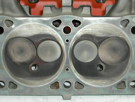
I have the chance (don't know about the energy though  ) to do another dyno test of Singh grooves on a SB Mopar engine. I'm wondering if someone could run CFD analysis of the cylinder head groove since it seems to me groove placement so far has been a "best guess" approach, so I wonder if CFD run would help with groove placement.
Do you want the groove to stir up the hottest or coldest part of the chamber? Where does detonation start the hottest part of the chamber or the coldest? Or both?
If I do this test it would be very similar to that last one but with the addition of steady state tests, both WOT and part throttle, and at various RPMs to nail down more accurate BSFC numbers. One other thing I'd like to try is run the octane down to actual detonation without grooves to test if the grooves supress detonation on the dyno.
Further ideas or comments might be appreciated.
Some quick references;
To Detonate or not to Detonate ?????
pre-ignition / detonation(post ignition)
Quench "flame channels" in piston vs. head quench
Singh grooves in cylinder head
what do you guys think of this? (the long grooves thread)
Dodge 360 Grooves Testing, 2-17-06.