Page 2 of 3
Re: Calculating effective intake runner length (siamesed intake port)
Posted: Sun Feb 04, 2018 12:08 am
by DrillDawg
My mistake, those figures where taken at .053", not .050", you would have to add "maybe" 20 more degrees to the opening and closing points.
Re: Calculating effective intake runner length (siamesed intake port)
Posted: Mon Feb 05, 2018 7:50 am
by enigma57
Thanks, hoffman900! Thanks, DrillDawg! That really puts an interesting spin on things! I'll see if I can utilize this to advantage on my engine build. Will be sure to let you know what Mike's take is on it as well when I reach that point.
My engine is a Chevy 292 inline 6 with cylinders numbered 1 - 6, #1 being the cylinder nearest front of engine. Firing order: 1, 5, 3, 6, 2, 4. Think of the engine architecture as being similar to an old Holden 202 red engine with 9-port head, but having around 1/3 more displacement.
My intake separates the engine into 3 groupings of paired ports (siamesed in head and in last inch and a half of intake where intake interfaces with head)...... 1 & 2, 3 & 4 and 5 & 6.
So from what you say, intake charge robbing would be first of the paired cylinders to fire robbing from the 2nd to fire, then?
That would result in #2 robbing from #1, #6 robbing from #5 and #4 robbing from #3 then? This should prove quite interesting indeed.
The following is excerpted from Leo Santucci's book......
"Flow Breakthrough
Headrick's breakthrough was understanding more fully than anyone before him the real nature of airflow in the Siamesed ports of the Chevy-six head. Jim was a fanatic when it came to testing and refining. Mike Kirby told me the Jin's team reputedly put over 100 additional hours into reworking the ports after he received the basic 'lump port' head from Sissel.
What Jim realized was that each port did not receive 50 per cent of the volume of that port, but rather, because the firing sequence never fired two adjacent cylinders, one cylinder actually was using the other Siamesed part of the port as a plenum, thus creating, in effect, a much larger port flow than one would expect. What Jim did and what was so unique for its time, was to change the timing events of the camshaft to take advantage of this 'larger port'. In effect, each cam lobe was ground on a different centerline so as you went from #1 cylinder to #6 cylinder some lobes were advanced, some were retarded. Jim shared with me that they interbred two different cam concepts to create enhanced airflow. To my knowledge, this design was never made generally available.
There were two elements that complemented the cam design. Through extensive dyno and airflow testing, Jim could produce over 319 CFM of airflow at 28" of water on the intake side. This was unheard of in 1978! In fact, it would take nearly 25 years before anyone figured out how to surpass these numbers with a stock-type head!
Flow Tips
First, Jim was adamant about three points:
1. If you go smaller than 64cc combustion chamber, you loose airflow.
2. Maximum size valves are:
Intake - 1.970"
Exhaust - 1.625"
Bore size imposes these limits
3. Velocity in the ports is critical.
Secondly, in order to support this airflow, more carburetion was needed as the power band moved into the higher RPM ranges (8,000 - 10,000 ROM). Several custom-made 3 X 2 sheet metal manifolds were devised and after extensive airflow testing, Jim settled on one that proved to provide more power than any other system available at the time.
Remember, these engines were all-our drag racing motors running in very tight power bands for limited times. Still, it is important to understand the fundamentals of power production - even though few of us would strive for this high level of horsepower production (estimated at over 650 HP)."
My Note: As my engine will be built for a road car, my goals differ significantly from a typical race engine build. I want to maximize torque production and average power over a broad power band. So will anticipate about 1/2 the HP and 85% of torque at peaks whilst holding redline a little over 1/2 the RPMs as Jim Headrick's race engine made. That said...... If I can understand and take advantage of some of the approaches Headrick and others pioneered to get a little more from this engine...... Last build for me...... I will be very happy indeed.

Best regards,
Harry
P.S. >>> I went over to Wallace Racing's calculators to check dimensions on the 3 carb intake I am building. CSA is spot on for 5,500 RPMs redline and runner length (measured through flow path from where runner joins plenum to back of intake valve, resting on its seat) is spot on for 3rd wave tune based upon cam I have in mind. A bit short based solely upon Helmholtz calcs alone, but apparently Wallace's calculator factors in duration of cam and that makes up the difference in this case. Wish I could take credit for that, but though the intake design is my idea, runner length and as cast CSA of the pieces I am using came out this way by sheer dumb luck more than anything.
Re: Calculating effective intake runner length (siamesed intake port)
Posted: Mon Feb 05, 2018 8:08 am
by mk e
On a 4cyl, pairing 1/2, 3/4 puts them 180 degrees apart and for sure 2 cylinders will be drawing at the same time.
With a 6 though 1/2,5/6 are 240 apart and 3/4 are 360 apart normally. There should be basically no effect in 3/4 and with modest duration cams only limited effect in 1/2, 3/4..... at least with air. If this was an efi engine fuel theft would still occur bit with carbs that shouldn't be a concern. This should work much better than a similar looking 4cyl setup.
Re: Calculating effective intake runner length (siamesed intake port)
Posted: Mon Feb 05, 2018 12:29 pm
by enigma57
...... With a 6 though 1/2, 5/6 are 240 apart and 3/4 are 360 apart normally. There should be basically no effect in 3/4 and with modest duration cams only limited effect in 1/2, 5/6......
Thanks, Mark! That's good to know. Unless Mike strongly recommends something else, I have planned on having my inline 6 cam ground similarly to the old Isky 274 Mega IMCA hobby stock hydraulic flat tappet grind for SBC (straight pattern cam, 226 deg, duration @ 0.050" and 0.490" lift on both, ground on 108 deg. LSA). The difference being that with 1.75 big block rockers on the inline engine, lift with same lobe will increase to 0.571". And I might tighten up LSA a degree or 2 as well. Need to discuss all this with MIke, but need to hold off until I am further along with headwork and short block. And of course, if Mike feels we can get sufficiently more out of this engine by varying lobe separation between individual cylinders to make the effort worthwhile, that is always an option.
Best regards,
Harry
Re: Calculating effective intake runner length (siamesed intake port)
Posted: Mon Feb 05, 2018 7:58 pm
by DrillDawg
I thought you where going for max torque around 5-5500 rpm, as that would make the most HP at the same rpm if you were not going to rev it above that. I guess the fancy intake system threw me off. An everyday 10 to 1 cr, head bolt boss removed, lump mod, 1.94 valve with a good cam will make 280 to 300 around 5-5500 rpm. You will loss some flow lift flow with the lump mod, but the gains above .400 lift more than make up for the low lift loss. It would be interesting to see what a finished port would flow with both valves open compared to just one valve at a time, that would tell if one cyl stealing a little flow would hurt the other cyl.
Re: Calculating effective intake runner length (siamesed intake port)
Posted: Tue Feb 06, 2018 6:28 am
by enigma57
Interesting! Especially your idea of flowing the finished siamesed port(s) with both valves fully open as well as with one valve closed. If I can swing that, I will test them that way. Perhaps install head and manifolds and actually measure valve lift of adjoining siamesed cylinder. Then test with one valve fully open and the other off its seat by same amount of lift as measured?
My goal for my 292 engine is to hold it at max 5,500 RPMs redline due to harmonics issues these engines are noted for at higher RPMs and maximize torque (averaged over a broad power band). Ran proposed engine specs by my youngest son the other day. He has one of those computer dyno programs. I am not sure I would trust it beyond predicting the difference certain changes might make to a given combination. But the engine responded well to a cam with specs same as the old Isky 274 Mega grind. At least on paper. Real world may be a different matter altogether.
Anyway, the torque and HP graphs went something like this......
Predicted torque curve was very broad. Never varied over 40 ft./lb.from 2,000 RPMs through 5,000 RPMs. TQ curve was nearly flat (within 10 ft./lb.) from 3,000 RPMs through 4,500 RPMs with peak TQ at 3,800 RPMs.
Predicted HP curve was not as broad as TQ curve of course, but was nearly flat (within 5 HP) from 4,500 RPMs through 5,700 RPMs with peak HP at 5,200 RPMs.
This simulation was with Isky 274 Mega grind same as Isky's V-8 specs (valve lift only 0.490" with 1.5:1 rockers - If running 1.75:1 big block rockers as most do with these reworked inline 6 iron heads, valve lift would increase to 0.571" and that would alter outcome a bit. But the main thing I wanted to see is whether this cam grind and general engine specs would put TQ and HP curves where I wanted them for this long stroke inline 6.
FWIW...... My son ran the simulation with 9.5:1 static comp. ratio, high perf. exhaust manifolds (not headers) with full muffled exhaust system...... And as there was no option to replicate the one off 3-carb intake setup I am building, he ran the program with a typical aftermarket single plane, common plenum log type intake and single 600 CFM 4bbl carb. I believe the intake I am putting together will boost TQ and HP a bit due to increased efficiency (through improved fuel distribution and metering) but the only way to know for sure is build it and run it.
Many thanks for your input and if you think of anything that might be helpful with this build, please let me know. This inline 6 with 9-port siamesed head is a much different animal from the V-8s and the inline 4's with cross flow 8-port heads I have worked with in years past.
Best regards,
Harry
Re: Calculating effective intake runner length (siamesed intake port)
Posted: Tue Feb 06, 2018 8:57 am
by DrillDawg
This is the way I look at it, torque and HP are equal at 5250, so the higher your torque is the higher your HP is at your rpm limit you set. A cyl. does not care how long the stroke is, it just cares how much air you can get in it at what rpm. Your limit on air flow is the cyl size and small combustion chamber. With a 1.94 valve and moderate porting you might be able to get 250 cfm at around .500 lift. The cyl. limits the valve size and the chamber limits the flow from the valve.
So keep the short block simple, torque plate hone, .035 to .040 head to piston clearance, dish in the piston the shape of the combustion chamber, modern thin rings. Head, use 5/16" valve stems, bee hive type springs, 1.94/1.55 to 1.60 valves, let your favorite head porter do his magic, 3/8" push rods, do everything you can to keep the fuel in suspension
Not only will the BB rocker open the valve more, it will open them farther sooner, so if there is anything too one valve stealing flow from the other valve at low lift, this might be something to think about.
Your best bet is to have the intake/cam/exhaust all tuned for the same rpm.
Re: Calculating effective intake runner length (siamesed intake port)
Posted: Wed Feb 07, 2018 6:41 am
by enigma57
Thanks, DrillDawg! That's pretty much what I have in mind for this last build. Looking at 0.040" quench (zero deck with 0.040" compressed thickness head gasket). Between 71cc and 74cc chambers and either flat top pistons or small (12cc or so) reverse dome (dish) in addition to deep valve reliefs. Will also look at possibly relieving bore above compression ring near valves to unshroud valves a bit. Cannot use offset dowels to move head and gain more clearance to cylinder wall, as intake and exhaust valve orientation alternate. Would like to run a set of LT4 valves I have here. They are 2.00"/1.55". Both hollow stemmed with sodium filled exhaust. But if I must run 1.94" intakes, will stay with the 1.94"/1.60" size most run in the reworked OEM iron head. Although I could have a machine shop turn the LT4 intakes down to 1.94", I reckon. On the beehive springs, I have never run them, but it is my understanding that LS3 springs and retainers will work. Will look into that.
Narrow rings...... Need to learn more about them. Same for the new style low tension rings. I have always run standard tension rings of OEM dimensions. Might try the new type rings if they will give good ring seal long term on a road car. If it comes to a compromise between ring seal and a small bit more friction in a running engine limited to the rev range I am building this engine for, though...... I will stay with the old school stuff I am used to. What are your thoughts on this? (Yes, I am an old guy and kinda set in my ways. Have no 'smart phone', don't text nor tweet nor whatever all that stuff is about. Reckon I've got along just fine without that stuff for 70 years now so no need to complicate my life with it at this point. So change doesn't come easy. But if there is an advantage to using thin rings and/or low tension rings...... I'll do it.)
Regarding matching up intake/cam/exhaust to engine for operating range it will be built for...... Agree 100%. I am using the same methodology I used when helping Dan Miller set up and tune his and Gene Adam's 2009 EMC entry which ran a set of EMPI (Weber IDA clone) carbs on loan from a VW racer and in working up CSA and tuned length for their 2010 and 2011 engines when rules changes forced us to come up with an EFI setup. Except that we had enough runner length for 2nd wave tuned length on Dan's hemi and it will be pretty tight getting enough runner length with my inline 6 for 3rd wave tuning. Still worth the effort, though.
Just want to make sure I understand the ins and outs of this siamesed port engine design so I can get the most out of it for what I am doing with it. Believe I have worked out a good baseline setup reconfiguring and rejetting the 42 DCNF carbs to work on plenum style intake as opposed to IR intake they were designed for. Want to get intake manifold as close as I can to 'right' so I can take advantage of 3rd wave tuning when it comes to runner length whilst still clearing master cylinder and steering column in my car. Need to get back on that before long. Need to cut a gasket for the DCOE flanges that will now be used to join the two intake halves. Then work out a way to incorporate engine coolant piping to heat/cool plenums beneath carbs, add small diameter balance tube connecting all 3 plenums. Then mount carbs and work up throttle linkage and fuel log. Air box with trunking and remote filters...... Or individual open element air cleaners...... All that will have to wait until I have engine completed and mounted in my car.
FWIW...... Had I not scored these 2 identical Brazilian made sidedraught intakes from a fellow at the HAMB and then figured out a way to put the 42 DCNF downdraught carbs I have here to good use when it became apparent DCOE sidedraughts won't clear master cylinder and steering column in my car...... For what I am doing, would likely have picked up a new Aussiespeed intake off e-Bay and ran a 625 cfm Street Demon 4bbl carb on this engine. I like the design of both. On the other hand...... If you like tinkering with carbs as I do...... 3 Webers on an inline 6 are just plain fun.
Best regards,
Harry
Re: Calculating effective intake runner length (siamesed intake port)
Posted: Wed Feb 07, 2018 8:46 am
by DrillDawg
Good luck. I'm assuming that the harmonics problem leads to slinging off the dampener, with that thought you might think about using an aftermarket dampener and machining the key slot as long as possible in the dampener and on the crankshaft for a longer key and then tap the end for the crankshaft for a "bigger" bolt (1/2"?)
Re: Calculating effective intake runner length (siamesed intake port)
Posted: Thu Feb 08, 2018 7:45 pm
by enigma57
Thanks, DrillDawg...... Good points all. Torsional dampner will usually stay on the 292 engine if fitup (interference fit) is correct and crank is drilled and tapped for retaining bolt rather than relying solely on press fit similar to dampners on early small blocks. I have been considering whether it would be wise to machine dampner and nose of crankshaft for a 2nd keyway in addition to cutting existing keyway slot longer as you suggest. Yes, I have decided to adapt a Fluidamper for small block to the 292 to aid with the harmonics issue. Will also use longer aftermarket rods and Ross pistons that are fully 1/2 lb. lighter per throw (removes 6 lb. of weight from rotating assembly).
The harmonics issue with the long stroke 292 engines at engine speeds exceeding 5,000 RPMs with stock rods and pistons affects primarily retention of the manual flywheel on stick shift setups. Not as much of an issue with flex plate when running automatic transmission. I'm not into slush boxes and will only go that route if I must, as knees are pretty well shot. Thinking of retrofitting a hydraulic clutch master and slave cylinder to my car before I give serious consideration to an automatic trans, though.
First version of 292 flywheel and crank flange were identical to small block and big block Chevy. GM later increased flywheel retaining bolt size for the 292 from 7/16" to 1/2" and went to 3 locating dowels rather than a single dowel in an effort to keep from slinging flywheels at higher RPMs. Leo Santucci in his book, recommends using 1/2" ARP flywheel bolts (Pontiac V-8 application).
The short deck, short stroke 194/230/250 engines apparently do not have the same harmonics issues as do the long stroke 292s with their heavier reciprocating parts.
Best regards,
Harry
Re: Calculating effective intake runner length (siamesed intake port)
Posted: Thu Feb 08, 2018 10:05 pm
by Leftcoaster
enigma57 wrote: ↑Wed Feb 07, 2018 6:41 am
Cannot use offset dowels to move head and gain more clearance to cylinder wall, as intake and exhaust valve orientation alternate.
Best regards, Harry
Are the port walls, valve guide support material, and valve pockets thick enough, and distance between valves large enough, that you can alternate offsetting intake then exhaust valve towards the other, to gain cylinder wall clearance for the displaced valve?
Re: Calculating effective intake runner length (siamesed intake port)
Posted: Fri Feb 09, 2018 4:14 am
by enigma57
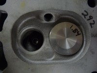
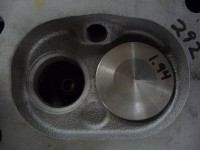
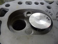
The 230/250/292 Chevy inline 6 shares a few things with the old 283 V-8 (bore size, valves, valve springs). And like the 283, has a smallish 3.875" (standard) bore and 1.72"/1.50" valves. Increasing to 1.60" exhaust is usually not an issue, but some head castings are thin enough that 1.84" (305 size) intakes are the largest that can be fitted without hitting water whilst other castings can take 1.94" intakes (with valves in original locations). So whilst there is enough space between valves to move valve guides closer (inboard) a few thousandths and gain a small bit of added clearance (valve heads to cylinder wall) when head is installed...... There is definitely a risk of hitting water once you rework the valve pockets and seats for the larger valve sizes and begin porting the head.
Here is a 230/250/292 head priour to machining for larger valves......


1.84" intake valve trial fitted without machining and unshrouding......
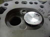
1.94" intake valve trial fitted without machining and unshrouding......
Here is a 250 block with flat top pistons (for turbo setup). Pistons are down in the hole a bit at TDC (I will zero deck mine), but you can see where cylinder walls have been relieved (above compression ring at TDC) as part of unshrouding when fitting larger valves......

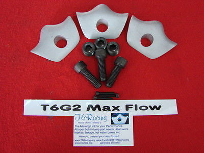
And here are the siamesed intake ports before and after removing headbolt boss running through them and fitting bolt-in lump port kit......


Best regards,
Harry
Re: Calculating effective intake runner length (siamesed intake port)
Posted: Sat Feb 10, 2018 2:21 pm
by DrillDawg
I would not run any "hot" water to the intakes as the header will provide all the heat you need, and maybe some that you don't. Also I would not run a balance tube between the intakes, if you did it would just provide another tuning variable and no real advantage. You have the chance to tune each set of cyls. on their own and with each cyl. of one pair more than likely wanting something different. They make a special device that you hold up to each carb inlet to measure air flow so that you can balance each cyl to it's pair and then to the other pairs, each cyl/pair, one at a time.
The tune will have a lot to do with the harmonics that your worried about. The chaos of feeding two cyls. with one port leads to uneven cyl. pressure which leads to the harmonics with your long stroke/rpm/ect. Just my thoughts, no need to debate.
Re: Calculating effective intake runner length (siamesed intake port)
Posted: Thu Feb 15, 2018 6:50 am
by enigma57
Thanks for your thoughts on this, DrillDawg. No debate here. Just sharing thoughts and looking for other's perspectives on this. Appreciate your comments.
I do have an old (bought it in the late '70s) uni-sync tool here which has served me well over the years. Will likely pick up one of the newer and more easily calibrated synchronomers such as the one marketed by Redline Performance, though. Have also considered making up a manometer setup to aid in tuning multiple carbs (giving some thought to that).
I understand your concern regarding adding a balance tube to interconnect the 3 small plenums...... If I do that, it will be a small diameter tube (likely 3/8" OD / 1/4" ID) and only used to smooth out idle and off idle running. Not large enough to really share air/fuel mixture between the 3 carburettors, but only to balance vacuum beneath throttle blades at and near idle (tickover). As it would be a tuning experiment, I would add a ball valve between each of the 3 plenums, each of which could be opened, closed or only partially opened (throttled back) to observe the effects as I dial in tuning and road test. And if no positive results come of it, I would remove the entire tubing setup and plug the holes. Both the '74 Aston Martin and the '80 Maserati IR intakes I have here utilize such a device (small interconnecting vacuum sharing passages below throttle blades), although each OEM manufacturer went about it in an entirely different manner and neither incorporates valves as I envisioned.
On regulating heat to the plenums beneath carbs (both heating and cooling)...... I have had good results using thermo base plates to circulate engine coolant beneath carburettors on road cars since the late '70s. May not have hood clearance in this instance to make up a set of thermo base plates such as that, though. So am considering running engine coolant through tubing in direct contact with underside of plenums to accomplish the same thing. In past engine builds, I have found thermo base plates to aid in atomization and drivability (from heating) and to cool (limit heat) to carbs and eliminate fuel boiling in bowls from too much underhood heat, as well. Still thinking about this. Could always run thin phenolic spacers beneath carbs and make up heat shields from sheetmetal and place them between intake and exhaust manifolds, but that would not keep temps at carbs as uniform and as close to 180 degrees as I would like. Will take another look at this as the intake comes along.
Also have some adjustable idle (slow running) jets here to experiment with that were made for other Weber applications (Fiat 500 Topolino from 1947 through 1961 with Weber IMB carb). Have a friend who has tried them with the single Weber DCNF carb he has fitted to his V-4 Saab and has had good luck with them as a tuning aid. As luck would have it, these will fit the Weber DCNF and IDF carbs, as well. Managed to score some (NOS) off e-Bay last year from a fellow in Poland......

Best regards,
Harry
Re: Calculating effective intake runner length (siamesed intake port)
Posted: Sun Mar 04, 2018 1:03 pm
by roc
Hey Harry, I'm following your progress closely, really nice work.
Here'a a video you might enjoy:
https://youtu.be/5ay3fW35sow