Question on Flowbench design
Moderator: Team

Re: Question on Flowbench design
Maybe some clues as to why highly-developed engines, e.g. Pro Stock, are trending to less overlap.
Felix, qui potuit rerum cognscere causas.
Happy is he who can discover the cause of things.
Happy is he who can discover the cause of things.
-
David Redszus
- Guru

- Posts: 9633
- Joined: Tue Nov 27, 2007 9:27 am
- Location: Chicago
- Contact:
Re: Question on Flowbench design
Good point. In the above example, it seems like the exhaust valve could have been closed a bit earlier without a noticible effect.MadBill wrote:Maybe some clues as to why highly-developed engines, e.g. Pro Stock, are trending to less overlap.
What we are not yet considering is the actual overlap by-pass orifice area (based on valve size and lift during overlap) and flow coefficients. In addition, I suspect that there are physical limitations based on camshaft/valve train capabilities such as closing, opening velocities and accelerations that must be considered.
And then we have the issue of overlap behavior at partial throttle; not a problem for drag racing but certainly for road and oval racing it should be considered.
I think that OEM engine designers might have other objectives on their plates such as emissions, fuel economy, throttle response, besides simply maximum power production.
-
Erland Cox
- Guru
- Posts: 4162
- Joined: Sun Jan 29, 2006 9:46 pm
- Location: Lund in Sweden
- Contact:
Re: Question on Flowbench design
According to a Dynomation simulation on a Volvo engine it has above Mach 0.25 in the intake port at TDC from 4750 to 7000 rpm.
Erland
Erland
-
David Redszus
- Guru
- Posts: 9633
- Joined: Tue Nov 27, 2007 9:27 am
- Location: Chicago
- Contact:
Re: Question on Flowbench design
A Mach number is a unit of speed and not pressure. Does it show inlet port pressure and cylinder pressure?Erland Cox wrote:According to a Dynomation simulation on a Volvo engine it has above Mach 0.25 in the intake port at TDC from 4750 to 7000 rpm.
Erland
Or, does it even show the direction of flow. In many engines with poor exhuast blowdown scavenging, the flow at TDC is reversionary. Blair wrote about this as a factor of charge purity, wherein reversionary exhaust gas is sucked into the chamber with a reduced purity.
-
Erland Cox
- Guru
- Posts: 4162
- Joined: Sun Jan 29, 2006 9:46 pm
- Location: Lund in Sweden
- Contact:
Re: Question on Flowbench design
I know that but I wanted to show what the combined pressures resulted in.
Dynomation gives a lot of pressures and other data like flow direction.
http://www.motionsoftware.com/Dynomation5.htm
Vanniks software is even better, maybe he can show something?
Erland
Dynomation gives a lot of pressures and other data like flow direction.
http://www.motionsoftware.com/Dynomation5.htm
Vanniks software is even better, maybe he can show something?
Erland
-
David Redszus
- Guru
- Posts: 9633
- Joined: Tue Nov 27, 2007 9:27 am
- Location: Chicago
- Contact:
Re: Question on Flowbench design
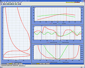
Erland, what is very interesting to examine is the light spring diagram that is shown on the left side. It shows chamber pressure being sub-atmospheric all the way to BDC on the induction stroke. An overlay of light spring diagrams for various engines (and valve timings) would be most informative.Erland Cox wrote:I know that but I wanted to show what the combined pressures resulted in.
Dynomation gives a lot of pressures and other data like flow direction.
http://www.motionsoftware.com/Dynomation5.htm
Vanniks software is even better, maybe he can show something?
Erland
-
vannik
- HotPass

- Posts: 539
- Joined: Sat Apr 10, 2010 10:23 am
- Location: Centurion, South Africa
- Contact:
Re: Question on Flowbench design
Dawid, what do you mean with "light spring diagram"? - is it the PV-diagram?
I have not followed this thread so some belated comments. The next picture shows my comment on the pressure traces of Blair:
The following shows Dawid's comment about the small orifices at small valve lifts. It shows the port mach number and the corresponding mach number at the valve seat:
And to complete the picture the following shows the mass flow through the curtain area:
Hope this is informative.
Vannik
You do not have the required permissions to view the files attached to this post.
“Ignorance more frequently begets confidence than does knowledge.” -Charles Darwin, The Descent of Man
-
Bob Hollinshead
- Guru
- Posts: 1481
- Joined: Thu Feb 07, 2008 1:32 pm
- Location:
Re: Question on Flowbench design
page 22 diagram 2.8 in Vizard's port and flow test book shows velocity at the seat in relation to crank rotation and overlap and cylinder pressure, even at TDC it shows 120FPS. Page 27 graph 3.4 shows another test, with the intake valve only .050 off the seat and the exhaust is pulling 100" of vacume, velocity is 200fps.
Pro question poster.
-
David Redszus
- Guru
- Posts: 9633
- Joined: Tue Nov 27, 2007 9:27 am
- Location: Chicago
- Contact:
Re: Question on Flowbench design
Yes it is. Early textbooks by Taylor and Heywood often referred to the PV diagram as a "light spring indicator diagram", perhaps based on the experimental aparatus used at the time. Later replaced by piezio sensors. The cylinder pressure at overlap shows cylinder pressure during overlap but does not indicate port pressures. Air flow can and does go in more than one direction.Dawid, what do you mean with "light spring diagram"? - is it the PV-diagram?
Your graphs are very useful indeed.
It is necessary to focus attention to the area between IVO and EVC, which represents the overlap period.
In almost all of my calculations a strong reversionary flow (with very high Mach numbers) occurs at IVO. But the flow aperature is very small and the reversionary mass flow rate not great but substantial. This reversionary flow clearly affects charge purity regardless of what occurs afterwards.
The other point to consider is that we have a triad of pressures to consider; inlet, cylinder and exhaust. More important, it is not their absolute pressures but their pressure ratios relative to each other that determines flow characteristics.
Another area to consider. If reversionary flow exists, and if charge shortstopping exists, there will be increased carbon deposits on the backside of the inlet and exhaust valves respectively. Who has not seen that?
-
Leftcoaster
- Pro

- Posts: 454
- Joined: Sat Jun 04, 2011 5:46 pm
- Location: Canada
Re: Question on Flowbench design
One Holy Grail unmaskedDavid Redszus wrote: The other point to consider is that we have a triad of pressures to consider; inlet, cylinder and exhaust. More important, it is not their absolute pressures but their pressure ratios relative to each other that determines flow characteristics.

Re: Question on Flowbench design
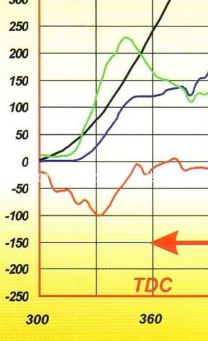
This is a zoom of one of the earlier mentioned graphs. It is from a SBC at 5500 rpm. (Peak torque & V.E. I think).
It seems to have enough header suction at overlap at this rpm, as the port and seat don’t flow backwards until IVC.
The red line is cylinder pressure in inches of water.
Blue is port velocity in ft/s
Green is velocity at the valve seat in ft/s
Black is intake valve lift in thousands of an inch.
It seems to have enough header suction at overlap at this rpm, as the port and seat don’t flow backwards until IVC.
The red line is cylinder pressure in inches of water.
Blue is port velocity in ft/s
Green is velocity at the valve seat in ft/s
Black is intake valve lift in thousands of an inch.
"I promise you Sheriff, I won't throw one more rock... Didn't say nothin' 'bout no brick!" --Ernest T Bass
Re: Question on Flowbench design
I think the one thing that is often over looked in regards to this is how fast this happens.MadBill wrote:I'd interpret it a little differently David.
IVO: At zero thous intake lift, cylinder pressure is higher than intake, but is dropping rapidly and exhaust is lower, so as enough lift to support significant flow develops, intake flow will initially be into the exhaust port. (cylinder purge) By ~ 30° BTDC, cylinder pressure has dropped below inlet pressure, promoting flow into the cylinder
TDC: I concur, but keep in mind for most applications a bit of over-scavenge is a good trade-off if it accommodates valvetrain dynamics and thorough cylinder purging, not to mention the previously discussed beneficial early establishment of inlet flow.
EVC: True, the inlet to cylinder delta is now fairly low, but that's about all there is to pull in the charge all the way to IVC. (In fact the pressure delta is higher between 30°BTDC and TDC than anywhere else in the stroke down to BDC.)
Please Note!
THE ABOVE POST IN NO WAY REFLECTS THE VIEWS OF SPEED TALK OR IT'S MEMBERS AND SHOULD BE VIEWED AS ENTERTAINMENT ONLY...Thanks, The Management!
THE ABOVE POST IN NO WAY REFLECTS THE VIEWS OF SPEED TALK OR IT'S MEMBERS AND SHOULD BE VIEWED AS ENTERTAINMENT ONLY...Thanks, The Management!
Re: Question on Flowbench design
A smaller chamber and higher rpm needs less overlap to scavenge the chamber and create the needed negative pressure area this is why most higher compression race engines will need a wider LSA than your average 10.1 street counter part.MadBill wrote:Maybe some clues as to why highly-developed engines, e.g. Pro Stock, are trending to less overlap.
Please Note!
THE ABOVE POST IN NO WAY REFLECTS THE VIEWS OF SPEED TALK OR IT'S MEMBERS AND SHOULD BE VIEWED AS ENTERTAINMENT ONLY...Thanks, The Management!
THE ABOVE POST IN NO WAY REFLECTS THE VIEWS OF SPEED TALK OR IT'S MEMBERS AND SHOULD BE VIEWED AS ENTERTAINMENT ONLY...Thanks, The Management!
Re: Question on Flowbench design
But yet the racers stuck on CFM are able to make massive improvements over what the factory and auto research labs continually produce.David Redszus wrote:Only factory programs and auto research labs.piston guy wrote:So is anyone porting heads with this technology?
Most racers are stil stuck on CFMs.
Please Note!
THE ABOVE POST IN NO WAY REFLECTS THE VIEWS OF SPEED TALK OR IT'S MEMBERS AND SHOULD BE VIEWED AS ENTERTAINMENT ONLY...Thanks, The Management!
THE ABOVE POST IN NO WAY REFLECTS THE VIEWS OF SPEED TALK OR IT'S MEMBERS AND SHOULD BE VIEWED AS ENTERTAINMENT ONLY...Thanks, The Management!

Re: Question on Flowbench design
A fascinating and informative discussion for sure
Only thing I can offer is that 4C330 is a poor choice for a flow bench vacuum source. It will not produce enough pressure.
Only thing I can offer is that 4C330 is a poor choice for a flow bench vacuum source. It will not produce enough pressure.