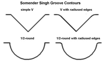
I have had lengthily discussions with Somender Singh about groove design, layout, theory and results. He has been involved with this for over ten years so he has plenty of experience. I remember him recommending leaving the edges of the groove at the deck surface sharp with no radius, as a result I have never tried the radius edge.MadBill wrote:...It would be a bit of a pain to form, but some kind of gentle down-slope across the squish band towards the groove(s), with a bit of a radius ('airbell') at the groove itself, might greatly increase the jet's volume and velocity....
Before/After grooved head pictures
Moderator: Team
-
automotive breath
- Guru

- Posts: 1681
- Joined: Sun Aug 28, 2005 11:54 pm
- Location:
-
Ed-vancedEngines
Panic,
Thnks for sticking with a thread and leaving your posting up. I came very close to copying it and posting it to be able to save it. I am joking but half serious too.
Your ideas and opinions here are valued as much as anyone else in this thread.
Beth,
Same with you, and your ideas and opinions. I hope you know that I consider you a very worthy contributor here and I do want to see what you ideas and thoughts are too.
I am only a member here like many of you are, but "Cotten-Picken-On-It" I have invested quite a lot of my time here and so have many of you, so I feel that I should have a little bit of a say-so here and also so should others who contribute and invest time here. With that said. I, on the behalf of all other contributing members do not want to see anyone peed-on here or talked negative to.
We are all here sharing with one another and are in the journey of learning curves here together.
Ed.
Thnks for sticking with a thread and leaving your posting up. I came very close to copying it and posting it to be able to save it.
Your ideas and opinions here are valued as much as anyone else in this thread.
Beth,
Same with you, and your ideas and opinions. I hope you know that I consider you a very worthy contributor here and I do want to see what you ideas and thoughts are too.
I am only a member here like many of you are, but "Cotten-Picken-On-It" I have invested quite a lot of my time here and so have many of you, so I feel that I should have a little bit of a say-so here and also so should others who contribute and invest time here. With that said. I, on the behalf of all other contributing members do not want to see anyone peed-on here or talked negative to.
We are all here sharing with one another and are in the journey of learning curves here together.
Ed.
-
automotive breath
- Guru
- Posts: 1681
- Joined: Sun Aug 28, 2005 11:54 pm
- Location:


-
mpgmike
I have done the radiused V:panic wrote: I suggested last year that the groove contour may not have been optimized, and that other shapes in cross-section might have an effect:
but no feedback.
An easy cut to make for volume and aero I would think are a simple U-groove beginning at the far end at zero depth and descending into the floor until you reach either the maximum safe depth (water) or lateral alignment with the plug electrode. Then, overlay a V to bevel the upper edges, then blend into the floor.
http://www.fueleconomytips.com/index.ph ... &Itemid=43
...and the radiused 1/2 round:
http://powrehaus.com/index.php?option=c ... ey=0&hit=1
I place the head on the mill at about a 5* angle, start at the gasket surface and pull. The groove deepens as it gets closer to the chamber. Afterwards I debur the sharp edges with a 120 grit sanding roll on the grinder.
Mike
Well how about angling both off them for reinforced swirl turbulence in order to enhance the perhaps (as i do not know the particular head) allready existing port bias??automotive breath wrote:If I had these heads to modify, I'd cut grooves in the location shown.
cheers
There is always advancement to be made.
-
Windsor377

- Expert

- Posts: 810
- Joined: Sat Apr 29, 2006 9:02 pm
- Location: Maryland
- Contact:
The conclusions I can draw at this point, based on the imformation provided here and in ABs earlier thread are:
1. The taperd fire deck/slant squish primarily helps combustion and is not necessarily a contributor or hindrance to flow.
2. The simplest approach to the grooves seems to be very effective in helping combustion.
3. Spark plug location seems to be the single biggest determining factor in groove location, irrespective of chamber design.
...hmmm...I feel like a need a set of "junk" Yates heads and a "junk" block that can still take a little power for some dyno testing...
I'd like to thank everyone for all the candid information.

I think we'll all be doing some testing 
This is the kind of stuff I came to this site for. Great tech info and little tips and tricks. Great stuff guys.
Is there a certain length or pitch to the groove we should aim for or just go from A to B with the longest line and taper from flat going to the top of the chamber?
This is the kind of stuff I came to this site for. Great tech info and little tips and tricks. Great stuff guys.
Is there a certain length or pitch to the groove we should aim for or just go from A to B with the longest line and taper from flat going to the top of the chamber?
-
automotive breath
- Guru
- Posts: 1681
- Joined: Sun Aug 28, 2005 11:54 pm
- Location:
I use a specific approach that is easy to do, effective and does not appear to jeopardize the integrity of the deck surface.John N wrote:Is there a certain length or pitch to the groove we should aim for or just go from A to B with the longest line and taper from flat going to the top of the chamber?
I draw the bore diameter on the deck surface then draw a straight line from the bore to the chamber between the valves directly in line with the spark plug. I cut the initial groove with a 1/16" ball end mill parallel with the deck surface about 0.080" deep (if the deck is thin as in some production heads I reduce the depth to 0.060" - 0.040").
I finish the groove with a hand held file and a hacksaw blade. I widen the groove outlet into the chamber to 0.125" and contour the bottom deep into the chamber. The idea is to direct squish flow up into the roof of the chamber.

-
DavidHarsay

- Pro

- Posts: 242
- Joined: Thu Apr 28, 2005 11:15 pm
- Location: Phoenix
I wonder if the indicated benefits of the grooves come from more of a mini vortex generator during the intake cycle... which produces a different type of turbulence than the tumble from airflow separation... as the air fuel mixture flows across the transition between the valve shroud and the quench pad? If that's the case, sharper groove edges are much more efficient, and also it would work better if the grove was pointed towards the intake valve.
This theory makes more sense in my mind than a squish/jet effect of some sort aimed at the spark plug. It's also seems to make more sense regarding the carbon coloring readings on the combustion chamber, and the domed pistons.
In my mind, it's also in line somewhat with Daren's wet flow work in the previous thread... but that's tougher to explain unless we get really in depth on aerodynamics, and transitions from laminar flow to airflow separation, and the effect that a sharp triangle has in such an area.
Along a similar thought, perhaps the sort of turbulence associated with the triangles aids in holding a more efficient homogeneous a/f mixture than the tumbling resulting from airflow separation.
As a side if someone has trouble visualizing what I'm indicating here, the leading edges of the Learjet model 60 have an area with a series of very sharp 1/2" long triangles. These triangles function to efficiently create tiny vortices, with which the airflow has more kinetic energy than laminar airflow, and it minimizes airflow separation (or tumble). For the Lear 60, when the angle of attack at high altitude cruise is in a critical area for controllability, this device allows the ailerons downstream of the triangles to function properly without the airflow separation which would render them ineffective.
Dave
-
larrycoyle
The only problem I have with this post is that it appears as though (and I will admit that I could have missed it) that other modifications were done at the same time as the grooves were installed. This doesn't make for a very good test in my opinion. I am not saying that these grooves do or do not work, I am only stating that to understand the real impact, the grooves should only be installed after you have a good baseline.
Larry
Larry
-
automotive breath
- Guru
- Posts: 1681
- Joined: Sun Aug 28, 2005 11:54 pm
- Location:
Your right Larry, the heads were ported at the same time that the grooves were cut, that's what the owner wanted. The intent here was to show how the burn covered the entire squish area after the modifications.larrycoyle wrote:The only problem I have with this post is that it appears as though (and I will admit that I could have missed it) that other modifications were done at the same time as the grooves were installed. This doesn't make for a very good test in my opinion. I am not saying that these grooves do or do not work, I am only stating that to understand the real impact, the grooves should only be installed after you have a good baseline.
Larry
I will be providing controlled groove tests eventually. At the present I'm learning as much as I can to assure the tests are meaningful. At this point two ideas interest me most, determining if the groove allows more compression with out detonation and if maximum power is made at a leaner air/fuel ratio.
-
BritishTurbo
- Member

- Posts: 98
- Joined: Sun Dec 04, 2005 2:34 pm
- Location:
I tend to agree... this whole "groove" business needs some scientific testing... I've talked with many of the "big names" on this board... the ones that aren't posting in this thread... and they all tend to disagree with some of the findings..
So it needs some true scientific before and after testing. If there is anything to this "groove" theory... then great, lets find out what it is... if not, then lets put it to bed
Also, all this talk had been about 2 valve heads... what about on a 4 valve head?
So it needs some true scientific before and after testing. If there is anything to this "groove" theory... then great, lets find out what it is... if not, then lets put it to bed
Also, all this talk had been about 2 valve heads... what about on a 4 valve head?
Lee
www.CENTROIDCNC.com
www.CENTROIDCNC.com
-
automotive breath
- Guru
- Posts: 1681
- Joined: Sun Aug 28, 2005 11:54 pm
- Location:
What findings are questioned?BritishTurbo wrote:I tend to agree... this whole "groove" business needs some scientific testing... I've talked with many of the "big names" on this board... the ones that aren't posting in this thread... and they all tend to disagree with some of the findings...
I haven’t done one, I have one to do on a Toyota but I havn't found the time to pull itBritishTurbo wrote:What about on a 4 valve head?
-
BritishTurbo
- Member
- Posts: 98
- Joined: Sun Dec 04, 2005 2:34 pm
- Location:
It has been questioned if the "groove" idea does anything at all of benefit... Some say all it does is increase chance of detonation...automotive breath wrote:What findings are questioned?BritishTurbo wrote:I tend to agree... this whole "groove" business needs some scientific testing... I've talked with many of the "big names" on this board... the ones that aren't posting in this thread... and they all tend to disagree with some of the findings...
I have one to do on a Toyota but I havn't found the time to pull itBritishTurbo wrote:What about on a 4 valve head?
I'm just asking for scientific investigation...
Lee
www.CENTROIDCNC.com
www.CENTROIDCNC.com
-
automotive breath
- Guru
- Posts: 1681
- Joined: Sun Aug 28, 2005 11:54 pm
- Location: