Thank you very much. That was more helpful than you might imagine.#84Dave wrote:Yes....... the intake ports in the head flowed 197cfm, +/- 4cfm, with 25" across the bench before and after the modification. Corrected head flow changed little, that we could detect. The head was a 2.0L SOHC Ford with 1.800" intakes and 1.450" exhausts. Dave
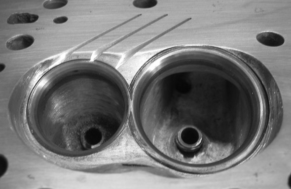
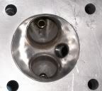
Before/After grooved head pictures
Moderator: Team
-
Windsor377

- Expert

- Posts: 810
- Joined: Sat Apr 29, 2006 9:02 pm
- Location: Maryland
- Contact:

Some idle thoughts:
2-stroke engines have been using slightly different angles for the 2 opposing quench surfaces for 30 years, about 2 degrees is common.
What does this do (separating the surfaces as they approach the open chamber area)?
The tighter quench may only be needed where the distance to the ignition source is greatest, and opening it as it becomes less critical may reduce pumping loss from the quench volume.
Has anyone done/seen a wedge chamber with the quench surface aimed vertically at the plug, i.e., not horizontal? Or inclined in 2 planes and aimed at the exhaust valve as well?
If (as Singh insists) the end gasses leaving the grooves induce turbulence in the chamber, would a groove aimed away from center induce swirl as well?
I think there is some relationship between the quench area, length of the farthest point from the quench/open boundary, and the number of grooves. As the quench area, and the distance, increase more grooves are needed to "bleed down" the area effectively, yes?
Is this a method of reducing the quench velocity where the area and engine speed are high?
-
automotive breath
- Guru

- Posts: 1681
- Joined: Sun Aug 28, 2005 11:54 pm
- Location:
The only people that I am aware of using this on race engines are in southern Louisiana, that's where I introduced the idea two years ago. I have done more than 20 sets of heads, about 2 - 3 sets a month now. My work has been exclusively on the wedge chamber only because that’s all we run.
I modified my Suburban last year, it is used primarily to pull my enclosed trailer to the track. I milled the heads 0.050" to raise the compression one point and cut the grooves. I have been very pleased with the results, no knock retard running 87 regular pulling 7000 lbs.

The best sites to read about current activity are http://forums.turbobricks.com/showthrea ... 370&page=2 and
http://mpgresearch.info/viewtopic.php?t ... .php?t=160
Anyone running a turbo will be interested.
I modified my Suburban last year, it is used primarily to pull my enclosed trailer to the track. I milled the heads 0.050" to raise the compression one point and cut the grooves. I have been very pleased with the results, no knock retard running 87 regular pulling 7000 lbs.
The best sites to read about current activity are http://forums.turbobricks.com/showthrea ... 370&page=2 and
http://mpgresearch.info/viewtopic.php?t ... .php?t=160
Anyone running a turbo will be interested.
On turbobricks Morten wrote:After 2 weeks of driving with the groves. This is my results. I'm able to use the same boost pressure on regular, as i had with premium petrol before. 220 kpa with the same timing.
Fuel consumption. Before 28 Mpg Imp. Best.
After 32 Mpg Imp and i'm still tuning.
AFR before at cruise 16-1 After at cruise 17.5-1 and nothing strange drivability problems. I'm going to try 18-1 next week if i can burn it.
So far i'm Happy.
BR
Morten
-
automotive breath
- Guru
- Posts: 1681
- Joined: Sun Aug 28, 2005 11:54 pm
- Location:
Diverging angles on squish areas are one of the ways to direct the squish flow and to slow squish flow velocity. Off horizontal plane squish areas can control squish direction without loss of velocity. 2 stroke engines and their 360 degree equal width squish bands direct flow to the center of the combustion space.
The squish width also controls squish flow direction, diverging angles can enhance the natural direction or change it.
The squish width also controls squish flow direction, diverging angles can enhance the natural direction or change it.

As I understand it, the value of large scale port-induced swirl is that during the compression stroke its energy decays into general turbulence.* If so, there might be negative benefit in developing a 'swirling jet' so late in the process. On the other hand...panic wrote:Some idle thoughts:
...If (as Singh insists) the end gasses leaving the grooves induce turbulence in the chamber, would a groove aimed away from center induce swirl as well?..
*(This might suggest that notoriously non-swirling heads, e.g. factory BBCs, would benefit disproportionately from grooving.)
On another tack, something that comes to mind in looking at the excellent shots of grooved heads here is consideration of the squish flow into the grooves. Observing this from a viewpoint parallel to the deck surface as the piston nears TDC, we would 'see' a sheet of rising velocity inflow from the squish area attempting to turn a sharp-edged corner into the groove 'canyon'. It seems to me this would result in considerable flow restriction, and the resulting pressure build up at the groove might cause much of the total squish flow to follow the path of least resistance direct to the combustion cavity, just as if there was no groove. This might also explain the observation that the grooves are often more effective when the squish clearance is well above the minimum for mechanical contact.
It would be a bit of a pain to form, but some kind of gentle down-slope across the squish band towards the groove(s), with a bit of a radius ('airbell') at the groove itself, might greatly increase the jet's volume and velocity.
A further thought would be that since piston/head contact usually occurs at the bore diameter, due to the inevitability of some piston rock, shaving a slight taper on the outer periphery of the piston deck might allow tighter clearance and force more of the squish flow through the groove.
Felix, qui potuit rerum cognscere causas.
Happy is he who can discover the cause of things.
Happy is he who can discover the cause of things.
-
larrycavan
- Expert
- Posts: 885
- Joined: Sat Jul 09, 2005 10:17 am
- Location:
- Contact:
-
Windsor377
- Expert
- Posts: 810
- Joined: Sat Apr 29, 2006 9:02 pm
- Location: Maryland
- Contact:
If hemi has a quench area now concentric with the bore and it works - propels a toroidal cloud up and into the chamber - radial grooves will disrupt it the least.
If not, the obvious spots are directly opposite the plug (last to get normal spark) and closest to the exhaust seat (hottest).
I suggested last year that the groove contour may not have been optimized, and that other shapes in cross-section might have an effect:
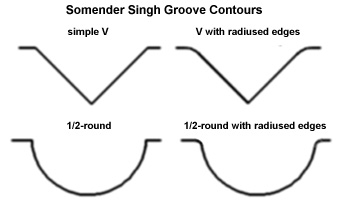
but no feedback.
An easy cut to make for volume and aero I would think are a simple U-groove beginning at the far end at zero depth and descending into the floor until you reach either the maximum safe depth (water) or lateral alignment with the plug electrode. Then, overlay a V to bevel the upper edges, then blend into the floor.
If not, the obvious spots are directly opposite the plug (last to get normal spark) and closest to the exhaust seat (hottest).
I suggested last year that the groove contour may not have been optimized, and that other shapes in cross-section might have an effect:
but no feedback.
An easy cut to make for volume and aero I would think are a simple U-groove beginning at the far end at zero depth and descending into the floor until you reach either the maximum safe depth (water) or lateral alignment with the plug electrode. Then, overlay a V to bevel the upper edges, then blend into the floor.
-
Windsor377
- Expert
- Posts: 810
- Joined: Sat Apr 29, 2006 9:02 pm
- Location: Maryland
- Contact:


Not to skip over Windsor377, but I like what Panic brought up. I like the radiused U getting deeper toward the plug (dead on or to one side of the plug? Would assume dead on with the electrode would be best?), but in which direction should the groove (I'm assuming one is enough at this point?) be pointing: toward the intake , toward the exhaust, or strait (all of which inline with the plug tip). I'm thinking of a small block Chevy head, but it shouldn't make much difference.