Cylinder head drainback lines

General engine tech -- Drag Racing to Circle Track

Moderator: Team

Kevin Johnson
HotPass
HotPass
Posts: 9399
Joined: Tue Nov 22, 2005 5:41 am
Location:

Re: Cylinder head drainback lines

Post by Kevin Johnson »

ptuomov wrote: Chrysler engineers call the driver side the suction side and the passenger side the pressure side. The small suction is generated by the rotation of the crankshaft.
I think it is more related to the deliberate offset of the crankcase volumes in many engines. Study the designs more and from more companies. The diffuser area allows pressure to build. Look at the Mopar Slant Six for example.

A V8 greatly complicates this but many high performance V8 pans still rely on the diffuser concept (large asymmetrical kickout).

ptuomov wrote: According to Chrysler simulation, their new 6.5L engine that is vented from the valve covers flows gas up continuously on the passenger side oil drains, while the direction of the gas flow in the driver side oil drains fluctuates with the engine cycle. As a side note, for a 6.5L V8 at 6000rpm, the piston pumping pulses are the elephant in the crankcase and the gas flow patterns due to crank rotation are of second order compared to piston pumping. This may be different for a small four banger, just talking about big V8's here.
With something like the Maybach HL 210 with directly opposing piston banks the crankshaft rotation would be less significant. With offset banks like in the Porsche V8 or Ford Modular V8 the rotation is highly significant in setting up flow patterns.
ptuomov wrote: I've also come to the opinion that it's not a productive exercise to try to get any scrapers as close to the crankshaft as possible in a big V8. The pressure differentials directly caused by the crankshaft rotation are not very significant.
Yes they are when the average droplet size allows gas flow to predominate in influence. This is not controversial.

Scrapers function differently at different RPMs. The flow allowed into the vortex in the Coyote valley feeds reduces the pressure differential and reduces the equilibrium level of oil droplet entrainment. A scraper approaches this task externally.
ptuomov wrote:If the scraper blocks the piston pumping pulses, the losses are likely a lot bigger than any benefits in reducing the crankshaft rotation pressures. The one thing that I think scrapers can help with is preventing oil from rebounding back to the crankshaft, and for that purpose it's much more important to get the scraper angle right than get it very close to the crankshaft. On a small four banger, this may also be different, just talking about big V8's here.
Directional screening is iterated scrapers. If the mesh size is appropriate it can be helpful in stopping droplet bouncing which tends to lead to droplet size reduction and greater oil entrainment. Ford did sponsor empirical testing of windage tray designs on a V6 at MIT. I think we have been over that a few times over the years. Some errors in the experimental design and analysis lead to recognizing both dedicated scrapers and well designed windage trays as being important.
https://www.semasan.com/breaking-news-archives?utm_campaign=DrivingForce_DF272&utm_content=SeeAllLeg
Cubic_Cleveland
Guru
Guru
Posts: 1163
Joined: Thu Feb 23, 2012 11:44 pm
Location: Australia

Re: Cylinder head drainback lines

Post by Cubic_Cleveland »

So just from your last paragraph Kevin, are you using directional mesh as a scraper and not using the more common solid scraper or solid scraper with louvers? If so, how do you find it works?
Kevin Johnson
HotPass
HotPass
Posts: 9399
Joined: Tue Nov 22, 2005 5:41 am
Location:

Re: Cylinder head drainback lines

Post by Kevin Johnson »

Cubic_Cleveland wrote:So just from your last paragraph Kevin, are you using directional mesh as a scraper and not using the more common solid scraper or solid scraper with louvers? If so, how do you find it works?
I have modified many solid factory trays with internal mesh and this works well to stop bouncing as well as the scouring effect that comes from large and/or rapid pulses (the screening helps shield draining oil). You need to study factory trays carefully preferably with a block at hand in order to see/understand the flow paths.

One of the most important things you can do is to closely examine well used parts WITHOUT CLEANING THEM. Doing this, for example, reveals the deleterious effects of the torque converter bolt access humps in a number of Nissan motors (RB26dett is severe). These are design elements forced onto the engineers.

Dedicated scrapers still give improvements when used in combination with trays. A dedicated scraper and windage tray have different demands made on them. Windage trays have diametrically opposed tasks which is why they are difficult to design well.
https://www.semasan.com/breaking-news-archives?utm_campaign=DrivingForce_DF272&utm_content=SeeAllLeg
Runit
Pro
Pro
Posts: 435
Joined: Mon Dec 26, 2011 10:10 am
Location:

Re: Cylinder head drainback lines

Post by Runit »

I have seen wet sump 2000 Pintos pump enough oil up thru the right rear head oil drain drain to fill the cam cover and push out the breather-filler cap.
User avatar
ptuomov
Guru
Guru
Posts: 3591
Joined: Fri Aug 07, 2009 3:52 am
Location:

Re: Cylinder head drainback lines

Post by ptuomov »

ptuomov wrote:Chrysler engineers call the driver side the suction side and the passenger side the pressure side. The small suction is generated by the rotation of the crankshaft.
Kevin Johnson wrote:I think it is more related to the deliberate offset of the crankcase volumes in many engines. Study the designs more and from more companies. The diffuser area allows pressure to build. Look at the Mopar Slant Six for example. A V8 greatly complicates this but many high performance V8 pans still rely on the diffuser concept (large asymmetrical kickout).
I disagree. In the simulations, the suction effect shows up even with a symmetric crankcase and oil pan and symmetric windage tray with simple symmetric holes.

It's either the crankshaft rotation directly or the one-two piston pumping pulses in which the passenger side piston serves the gas to the driver side which the punches it out. A bit like a one-timer in ice hockey. Regardless, it exists in a perfectly symmetric crankcase.
ptuomov wrote: According to Chrysler simulation, their new 6.5L engine that is vented from the valve covers flows gas up continuously on the passenger side oil drains, while the direction of the gas flow in the driver side oil drains fluctuates with the engine cycle. As a side note, for a 6.5L V8 at 6000rpm, the piston pumping pulses are the elephant in the crankcase and the gas flow patterns due to crank rotation are of second order compared to piston pumping. This may be different for a small four banger, just talking about big V8's here.
Kevin Johnson wrote:With something like the Maybach HL 210 with directly opposing piston banks the crankshaft rotation would be less significant. With offset banks like in the Porsche V8 or Ford Modular V8 the rotation is highly significant in setting up flow patterns.
I don't think the bore offset is significant. It's 25mm in Porsche 928, and less in most other motors. One could hypothesize that the bore offset causes a circular movement within a single bay. In the simulation data, though, the overall pumping movement completely overwhelms this effect. When the opposing piston sucks or pushes, the flow is in the same direction on both sides of the bay. The simulated flow thru the bearing side breather holes also doesn't support this theory. It's a good theory, but I don't think it's actually true if we limit ourselves to large-displacement 90-degree V8's.

Now, in an inline four, we probably see two simultaneous circular motions, one in bays 1&2 and another in 3&4, but that's a pure guess on my part and not based on any actual simulation data. But I could see that happening.
ptuomov wrote: I've also come to the opinion that it's not a productive exercise to try to get any scrapers as close to the crankshaft as possible in a big V8. The pressure differentials directly caused by the crankshaft rotation are not very significant.
Kevin Johnson wrote:Yes they are when the average droplet size allows gas flow to predominate in influence. This is not controversial.
I fail to see the relevance of droplet size here. Quantitatively, the gas flow caused by piston pumping is the elephant in the crankcase and everything else is a bunch of mice.

The below figures are from the simulation data set run with an asymmetric windage tray. The color coded velocity vectors indicate the speed at which gas flows at that point. Here's a cross-section of the front bay at 315 degrees on the crank:
Bay1Degrees315.JPG
You can see a minor effect of gas flowing with the crankpin near the crankpin. But you have to squint. The elephant in the room is the driver side piston unleashing the fury.

Below is the same bay at 225 degrees, 90 degrees earlier than the above graph. Now it's relatively calm there, so you can see the crankshaft rotation effects a bit more clearly. But it's still very minor compared to the piston pumping effects.
Bay1Degrees225.JPG
This with the caveat that these observations only apply to big 90-degree V8s. A small four banger might be a completley different story. As a side note, it seems to me that car factories use scraper-style devices more in small four bangers and less in big 90-degree V8s. But that's just a casual impression, you would know better.
Kevin Johnson wrote:Scrapers function differently at different RPMs. The flow allowed into the vortex in the Coyote valley feeds reduces the pressure differential and reduces the equilibrium level of oil droplet entrainment. A scraper approaches this task externally.
I agree that everything is different at low vs. high rpms. Gas flows aren't an issue at low rpms. More generally, as far is this site and audience goes, what happens at low rpms is pretty much irrelevant. There are no problems to be solved at low rpms, at least no problems of significance to this speedtalk.com crowd.

I enjoyed your Coyote writeup, by the way. After spending time with these simulation data, I would have approached that windage tray modification differently, however. Ford came to you saying that they lost power with the windage tray, and wanted to fix that. I would have fixed it simply by making the holes in the tray larger. You chose to fix it by adding more devices in there that restrict gas flow. I have no data on what your approach produced in terms of picking up the lost power. However, I conjecture from these simulations that the number one determinant of the power losses with the windage tray is the size of the holes. I have simulation data from a similar engine that says that larger holes add power and smaller holes reduce power, and the effect is significant. I also conjecture that stuffing the crankcase with more things that inhibit flow will increase power losses, not reduce them. That's just a conjecture.

Just an opinion, but I believe an informed opinion. if they sent you dyno data with your modified tray, it would be very interesting to see that.
ptuomov wrote:If the scraper blocks the piston pumping pulses, the losses are likely a lot bigger than any benefits in reducing the crankshaft rotation pressures. The one thing that I think scrapers can help with is preventing oil from rebounding back to the crankshaft, and for that purpose it's much more important to get the scraper angle right than get it very close to the crankshaft. On a small four banger, this may also be different, just talking about big V8's here.
Kevin Johnson wrote:Directional screening is iterated scrapers. If the mesh size is appropriate it can be helpful in stopping droplet bouncing which tends to lead to droplet size reduction and greater oil entrainment. Ford did sponsor empirical testing of windage tray designs on a V6 at MIT. I think we have been over that a few times over the years. Some errors in the experimental design and analysis lead to recognizing both dedicated scrapers and well designed windage trays as being important.
The car factories seem to hate those screens that you love. I don't know if this is for cost or reliability concerns, or if they have issues with performance.

My casual observation is that the aftermarket performance market is also moving away from mesh screens and towards solid trays with larger openings. I don't know if this observation is correct or not, but that's the impression I've gotten.
You do not have the required permissions to view the files attached to this post.
Paradigms often shift without the clutch -- https://www.youtube.com/watch?v=cxn-LxwsrnU
https://www.instagram.com/ptuomov/
Put Search Keywords Here
Kevin Johnson
HotPass
HotPass
Posts: 9399
Joined: Tue Nov 22, 2005 5:41 am
Location:

Re: Cylinder head drainback lines

Post by Kevin Johnson »

Tuomo,

Before we get into this too much further: what rpms do the sims represent?
https://www.semasan.com/breaking-news-archives?utm_campaign=DrivingForce_DF272&utm_content=SeeAllLeg
User avatar
ptuomov
Guru
Guru
Posts: 3591
Joined: Fri Aug 07, 2009 3:52 am
Location:

Re: Cylinder head drainback lines

Post by ptuomov »

Kevin Johnson wrote:Tuomo,Before we get into this too much further: what rpms do the sims represent?
6000 rpm, which is about the peak power rpm for this simulated 6.5 liter engine.
Paradigms often shift without the clutch -- https://www.youtube.com/watch?v=cxn-LxwsrnU
https://www.instagram.com/ptuomov/
Put Search Keywords Here
Kevin Johnson
HotPass
HotPass
Posts: 9399
Joined: Tue Nov 22, 2005 5:41 am
Location:

Re: Cylinder head drainback lines

Post by Kevin Johnson »

ptuomov wrote:
Kevin Johnson wrote:Tuomo,Before we get into this too much further: what rpms do the sims represent?
6000 rpm, which is about the peak power rpm for this simulated 6.5 liter engine.
I do not see rods, crank arms or counterweights. ?
https://www.semasan.com/breaking-news-archives?utm_campaign=DrivingForce_DF272&utm_content=SeeAllLeg
User avatar
ptuomov
Guru
Guru
Posts: 3591
Joined: Fri Aug 07, 2009 3:52 am
Location:

Re: Cylinder head drainback lines

Post by ptuomov »

Kevin Johnson wrote:
ptuomov wrote:
Kevin Johnson wrote:Tuomo,Before we get into this too much further: what rpms do the sims represent?
6000 rpm, which is about the peak power rpm for this simulated 6.5 liter engine.
I do not see rods, crank arms or counterweights. ?
That's because the cross-section is taken from the middle of the bay, slicing thru the crankpin in the middle. No simulation is perfect, but this is the most realistic by a large margin among those from which I've seen detailed results. The crankshaft and in particular the counterweights are modeled in detail, because they have a potentially large impact on gas flows between bays. The piston is modeled in a stylized fashion as a flat surface. The connecting rod is not modeled, on prior grounds that it's relatively unimportant to the gas flows.
Paradigms often shift without the clutch -- https://www.youtube.com/watch?v=cxn-LxwsrnU
https://www.instagram.com/ptuomov/
Put Search Keywords Here
Kevin Johnson
HotPass
HotPass
Posts: 9399
Joined: Tue Nov 22, 2005 5:41 am
Location:

Re: Cylinder head drainback lines

Post by Kevin Johnson »

ptuomov previously wrote:Chrysler engineers call the driver side the suction side and the passenger side the pressure side. The small suction is generated by the rotation of the crankshaft.
Kevin Johnson previously wrote:I think it is more related to the deliberate offset of the crankcase volumes in many engines. Study the designs more and from more companies. The diffuser area allows pressure to build. Look at the Mopar Slant Six for example. A V8 greatly complicates this but many high performance V8 pans still rely on the diffuser concept (large asymmetrical kickout).
ptuomov wrote:I disagree. In the simulations, the suction effect shows up even with a symmetric crankcase and oil pan and symmetric windage tray with simple symmetric holes.
I would have to say you're correct. I have just looked at a number of blocks/pans and can see designs that have either side larger so it would be incorrect to pick out just examples demonstrating one side. I think the diffuser idea is certainly used but not exclusively on the upstroke side. It would interesting to learn when and how the terms were first used.

ptuomov wrote: According to Chrysler simulation, their new 6.5L engine that is vented from the valve covers flows gas up continuously on the passenger side oil drains, while the direction of the gas flow in the driver side oil drains fluctuates with the engine cycle. As a side note, for a 6.5L V8 at 6000rpm, the piston pumping pulses are the elephant in the crankcase and the gas flow patterns due to crank rotation are of second order compared to piston pumping. This may be different for a small four banger, just talking about big V8's here.
More info is needed on the elements included in the simulation.
Kevin Johnson previously wrote:With something like the Maybach HL 210 with directly opposing piston banks the crankshaft rotation would be less significant. With offset banks like in the Porsche V8 or Ford Modular V8 the rotation is highly significant in setting up flow patterns.
ptuomov wrote: I don't think the bore offset is significant. It's 25mm in Porsche 928, and less in most other motors. One could hypothesize that the bore offset causes a circular movement within a single bay. In the simulation data, though, the overall pumping movement completely overwhelms this effect. When the opposing piston sucks or pushes, the flow is in the same direction on both sides of the bay. The simulated flow thru the bearing side breather holes also doesn't support this theory. It's a good theory, but I don't think it's actually true if we limit ourselves to large-displacement 90-degree V8's.
The witness marks in a full length Corvette LS windage tray show a majority of the ejected oil from the mains and rods being transported to the ends of the tray and this indicates a circulatory pattern between and along multiple bays. So perhaps the simulation needs more work? :wink:

ptuomov wrote:
Now, in an inline four, we probably see two simultaneous circular motions, one in bays 1&2 and another in 3&4, but that's a pure guess on my part and not based on any actual simulation data. But I could see that happening.
Yes, just look at the ZZ engine where the main axis of circulation is changed in 3-4.
ptuomov previously wrote: I've also come to the opinion that it's not a productive exercise to try to get any scrapers as close to the crankshaft as possible in a big V8. The pressure differentials directly caused by the crankshaft rotation are not very significant.
Kevin Johnson previously wrote:Yes they are when the average droplet size allows gas flow to predominate in influence. This is not controversial.
ptuomov wrote: I fail to see the relevance of droplet size here. Quantitatively, the gas flow caused by piston pumping is the elephant in the crankcase and everything else is a bunch of mice.


The mice cause more friction when they hit things and splatter than the elephant's breath.

...


Kevin Johnson previously wrote:Directional screening is iterated scrapers. If the mesh size is appropriate it can be helpful in stopping droplet bouncing which tends to lead to droplet size reduction and greater oil entrainment. Ford did sponsor empirical testing of windage tray designs on a V6 at MIT. I think we have been over that a few times over the years. Some errors in the experimental design and analysis lead to recognizing both dedicated scrapers and well designed windage trays as being important.
ptuomov wrote:The car factories seem to hate those screens that you love. I don't know if this is for cost or reliability concerns, or if they have issues with performance.
I think because of cost concerns. Porsche did not have any difficulties with screened sumps.

ptuomov wrote:My casual observation is that the aftermarket performance market is also moving away from mesh screens and towards solid trays with larger openings. I don't know if this observation is correct or not, but that's the impression I've gotten.
My casual observation is that many fabrication supplies are sourced from catalogs and custom mesh sizes that are not off the rack are ignored.
https://www.semasan.com/breaking-news-archives?utm_campaign=DrivingForce_DF272&utm_content=SeeAllLeg
Kevin Johnson
HotPass
HotPass
Posts: 9399
Joined: Tue Nov 22, 2005 5:41 am
Location:

Re: Cylinder head drainback lines

Post by Kevin Johnson »

Kevin Johnson previously wrote: I do not see rods, crank arms or counterweights. ?
ptuomov wrote:That's because the cross-section is taken from the middle of the bay, slicing thru the crankpin in the middle. No simulation is perfect, but this is the most realistic by a large margin among those from which I've seen detailed results. The crankshaft and in particular the counterweights are modeled in detail, because they have a potentially large impact on gas flows between bays. The piston is modeled in a stylized fashion as a flat surface. The connecting rod is not modeled, on prior grounds that it's relatively unimportant to the gas flows.
The rods might have a wee impact on the aerodynamics of the pin. Just a thought.
https://www.semasan.com/breaking-news-archives?utm_campaign=DrivingForce_DF272&utm_content=SeeAllLeg
User avatar
ptuomov
Guru
Guru
Posts: 3591
Joined: Fri Aug 07, 2009 3:52 am
Location:

Re: Cylinder head drainback lines

Post by ptuomov »

ptuomov wrote: I don't think the bore offset is significant. It's 25mm in Porsche 928, and less in most other motors. One could hypothesize that the bore offset causes a circular movement within a single bay. In the simulation data, though, the overall pumping movement completely overwhelms this effect. When the opposing piston sucks or pushes, the flow is in the same direction on both sides of the bay. The simulated flow thru the bearing side breather holes also doesn't support this theory. It's a good theory, but I don't think it's actually true if we limit ourselves to large-displacement 90-degree V8's.
Kevin Johnson wrote:The witness marks in a full length Corvette LS windage tray show a majority of the ejected oil from the mains and rods being transported to the ends of the tray and this indicates a circulatory pattern between and along multiple bays. So perhaps the simulation needs more work? :wink:

First, no simulation is perfect. If it were perfect, it wouldn't be a simulation, it would be the reality. This simulation however is good enough to be highly informative.

Second, I don't think there is any significant intra-bay circular flow pattern that is caused by bore offset. There's just no evidence of that.

Third, however, there are very interesting flow patterns between bays, some of which are curved. Perhaps this is what you are talking about. For example, here's a hand draw sketch of a flow pattern, drawn based on the numerical simulation values at 225 degrees of the crankshaft:
Crank225.jpg
At 225 degrees, there is a very strong gas flow from the driver side rear bay to the passenger side front bay. I believe the flow forms an S shape, transitioning over the two middle bays, in this particular case below the crankshaft in the oil pan. There are weak direct flows as well, but S is the elephant in the pan. This is an interesting crank degree for other reasons, too, as the crankcase gas flows up with a strong pulse in most oil drainbacks.
You do not have the required permissions to view the files attached to this post.
Paradigms often shift without the clutch -- https://www.youtube.com/watch?v=cxn-LxwsrnU
https://www.instagram.com/ptuomov/
Put Search Keywords Here
User avatar
ptuomov
Guru
Guru
Posts: 3591
Joined: Fri Aug 07, 2009 3:52 am
Location:

Re: Cylinder head drainback lines

Post by ptuomov »

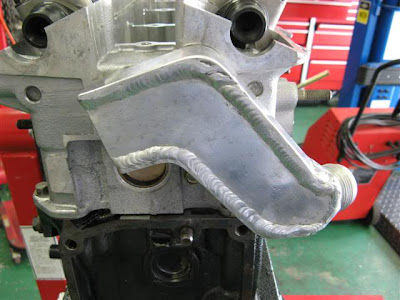
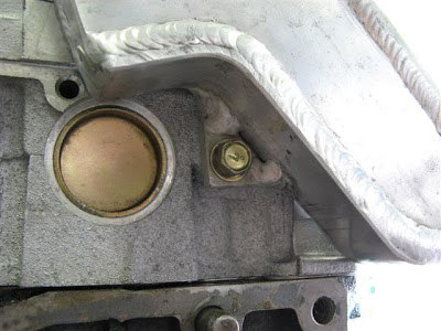
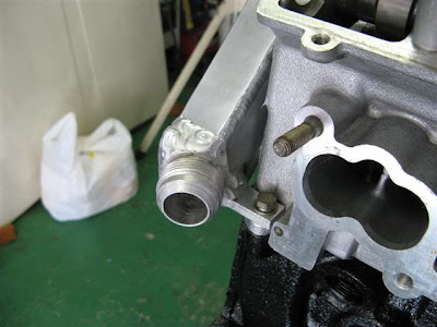
KnightEngines, is that hose to heads meant to drain oil down or flow gas up? The reason why I am asking is that I've come to the conclusion (from theory, no practical experience worth mentioning) that it's more important to get the gas flowing up with an added line so the existing drainbacks can do their work draining down. Just wondering about the purpose of those lines in that engine.

Here's a writeup by one Skyline GT-R guy about his extra line from the heads to the pan:

http://www.skylife4ever.com/2011/04/rb2 ... build.html

The following three pictures are of the additional crankcase vent. I first started doing this mod on the 26 in the mid 90’s. It’s a common mod for high rpm engines, so it was a no-brainer for the RB26. Soon thereafter, the Internet got a hold of it and speculation as to its function ran rampant. “Additional oil drain-back” became the consensus, and consensus became fact. Now it’s well known as the additional oil drain back mod… Then it became a fact that all the oil in the engine will pool in the head and the engine will blow if you don’t have it done…

Really? Let’s examine some facts. The RB26 has been lapping the Nurburgring starting years before the R32 came out in 1989. Lap after lap at full-boogie. Since then, the R33 and R34 have been lapping the same track. The N1 GT-R that races in the N1 class doesn’t have this mod done. Super Taikyu RB26’s don’t have this mod done. I can assure you that the RB26 does not have an oil drain back problem that warrants modification to implement an additional one.

On Youtube you can find some videos of the Porsche Turbo engines in a cradle that simulate a run of the Nurburgring to test the oil system. Nissan has the same thing.

So what’s the deal??

Windage and blow-bye in ultra-performance engines. You get an RB26 up in the 10,000rpm neighborhood and lean on it with 2+ kg of boost and you have a nightmare.

See, all but one of the oil drains back into the sump on the RB26 are on the left side of the block. When we examine crank windage, that’s the side of the engine where the crank counterweights, rods, etc., are moving in a downward direction, essentially “pulling” oil back down out of the head. In the right-rear of the engine, there’s another port. This port is on the “pressure” side of the motor, and windage blows up this passage, creating an actual suction on the drain-side of the motor.

At high-rpm, high-boost, windage and blow-bye gasses can be so severe, that the single port on the right side isn’t adequate. Gasses are moving up all the ports, sometimes at high velocity. This effectively keeps oil from returning to the sump. What the large hose from the sump to the back of the head does is give the blow-bye gasses another path to the head, and allow the oil to return down the normal returns along the left side of the motor. It needs to be above the oil level in the sump, but below the baffle.

In a drag motor, if we accelerate forward at 1g, the oil in the sump will stand up at 45 degrees. It’d be neat to hear an explanation of how the oil in the head overcomes the laws of physics and somehow runs forward to the front of the engine. In a circuit/touge motor like this one, oil will indeed return down the hose to the sump because not all of the acceleration is forward. This is the reason it needs to be lower than the baffles in the pan; on that side of the engine, any oil returning will simply be picked up by the crank and added to the hurricane in the crankcase.

Nissan Head Oil Return Drain mod
Image

Custom Nissan Head Oil Return Drain mod
Image

Aluminum Custom Nissan Head Oil Return Drain mod
Image

What we found was that under these extreme conditions, we were pumping a quart of oil out of the breathers and into the overflow in a 400m pass. Not only was it not returning, but the blow-by gases were pushing it out of the engine. Additional vent was added, and the problem disappeared. It needs to be said that in engines turning 9,000 rpm and boosting 1.7 bar, engines making north of 750hp, this "problem" has never presented itself. That, and the problems you can create if it's not done properly are the reason I've been so against it in more reasonable engines. An example is if you put the tube below the oil level in the pan, not only are you choking any venting action, you're giving the oil another place to go during acceleration. Like I said above, oil will leave the sump through the hose.

Hate away.
Paradigms often shift without the clutch -- https://www.youtube.com/watch?v=cxn-LxwsrnU
https://www.instagram.com/ptuomov/
Put Search Keywords Here
Kevin Johnson
HotPass
HotPass
Posts: 9399
Joined: Tue Nov 22, 2005 5:41 am
Location:

Re: Cylinder head drainback lines

Post by Kevin Johnson »

Better to start again.

Not all big V8 engines have deep block skirts.

Not all deep block skirt V8 engines have cross-bolted mains.

There is a wide amount of variation in the design of cross-bolted mains.

Even fewer big V8 engines have bedplates.

It appears that the 928 Porsche V8 had vestigal provisions for venting each bay to a plenum in the valley but these vents were not used in the production version. There are bay to bay ports that you are very familiar with.

The Coyote valley breathing port is handed (unlike in your sim).

Many large V8 engines are cam-in-block and this moving structure will influence intra and interbay flow.

The design of rods is important to windage flow.

The design of crankshaft counterweights is important to windage flow.

Etc.

~~~~~~~~~~~~~~~~~~

The openings in the windage tray for the Chrysler 6.5l motor that is the subject of the sims appear to be similar to the openings in the 5.7 tray which are a type of scraper. The Dodge 2.7 V6 has a more explicit example. There are numerous other examples from many other OEMs and engine families and architectures (inline and V).

~~~~~~~~~~~~~~~~~~
ptuomov wrote:I don't think the bore offset is significant. It's 25mm in Porsche 928, and less in most other motors. One could hypothesize that the bore offset causes a circular movement within a single bay. In the simulation data, though, the overall pumping movement completely overwhelms this effect.
The simulation is not a representation of what is occurring in a Porsche 928 V8.
ptuomov wrote:
First, no simulation is perfect. If it were perfect, it wouldn't be a simulation, it would be the reality. This simulation however is good enough to be highly informative.
The simulation is indeed interesting and informative.
ptuomov wrote:
Second, I don't think there is any significant intra-bay circular flow pattern that is caused by bore offset. There's just no evidence of that.
There are so many idiosyncracies in this one sim/engine compared even to the general class of large V8 engines, much less other engines, that there is no evidence to support the general claim of no evidence for circular flow patterns in intra-bay exchange.
ptuomov wrote:
Third, however, there are very interesting flow patterns between bays, some of which are curved. Perhaps this is what you are talking about.
Yes; my immediately previous remarks notwithstanding.
https://www.semasan.com/breaking-news-archives?utm_campaign=DrivingForce_DF272&utm_content=SeeAllLeg
User avatar
ptuomov
Guru
Guru
Posts: 3591
Joined: Fri Aug 07, 2009 3:52 am
Location:

Re: Cylinder head drainback lines

Post by ptuomov »

Kevin Johnson wrote:Not all big V8 engines have deep block skirts. Not all deep block skirt V8 engines have cross-bolted mains. There is a wide amount of variation in the design of cross-bolted mains. Even fewer big V8 engines have bedplates. It appears that the 928 Porsche V8 had vestigal provisions for venting each bay to a plenum in the valley but these vents were not used in the production version. There are bay to bay ports that you are very familiar with. The Coyote valley breathing port is handed (unlike in your sim). Many large V8 engines are cam-in-block and this moving structure will influence intra and interbay flow. The design of rods is important to windage flow. The design of crankshaft counterweights is important to windage flow.
These things will undoubtedly influence the speed at which gas flows, and consequently the severity of various problems, but apart from the Coyote inside breathing channels to the head, I don't think they are going to change the big picture flow patterns. What I found most informative about this simulation is what does not seem to matter. Nothing else matters very much to the crankcase gas flow patterns in a big V8 than the piston pumping action. For example, when one tests three very different windage tray designs, the flow rate thru the main bearing sides doesn't change in any meaningful way.
Kevin Johnson wrote:The openings in the windage tray for the Chrysler 6.5l motor that is the subject of the sims appear to be similar to the openings in the 5.7 tray which are a type of scraper. The Dodge 2.7 V6 has a more explicit example. There are numerous other examples from many other OEMs and engine families and architectures (inline and V).
The base case windage tray is very close to this one in the photo. The simulated pan is a simpler design but one of the windage trays is just like this:
Image

Although it's at this point a matter of semantics what is a scraper and what is not a scraper, I don't see a lot of "scraper like" devices in this particular windage tray. Luckily, given the fact that direct effects of crankshaft rotation are minor compared to the piston pumping effects, I don't see the scraper like devices being very relevant to the gas flows in a big V8.
ptuomov wrote:I don't think the bore offset is significant. It's 25mm in Porsche 928, and less in most other motors. One could hypothesize that the bore offset causes a circular movement within a single bay. In the simulation data, though, the overall pumping movement completely overwhelms this effect.
Kevin Johnson wrote:The simulation is not a representation of what is occurring in a Porsche 928 V8.
No, it's not. But seeing this simulation of an engine, which by the way has a crankcase that is pretty similar to a stroked 928 crankcase, caused at least me to have a couple of "aha" moments. I believe that there are some significant lessons here that are universally applicable to big cross-plane V8s. One of those lessons is that piston pumping is the main gas flow effect and direct impact of crankshaft rotation is small in comparison. Another lesson is that that the piston pumping effects are so large that I don't believe there can be any sort of important circular motion on the horizontal plane inside a single bay.
ptuomov wrote: Second, I don't think there is any significant intra-bay circular flow pattern that is caused by bore offset. There's just no evidence of that.
Kevin Johnson wrote:There are so many idiosyncracies in this one sim/engine compared even to the general class of large V8 engines, much less other engines, that there is no evidence to support the general claim of no evidence for circular flow patterns in intra-bay exchange.
I disagree. While this doesn't prove it for all big V8's, there's evidence to support the claim. In fact, pretty powerful evidence that shifted my views. Now, it's possible (although unlikely) that someone will come up with some additional evidence to shift my views again.
Paradigms often shift without the clutch -- https://www.youtube.com/watch?v=cxn-LxwsrnU
https://www.instagram.com/ptuomov/
Put Search Keywords Here
Post Reply